Product Overview
The High-Current IRF520 MOSFET Driver Board is a powerful and versatile electronic switch module designed to bridge the gap between low-voltage microcontrollers and high-power loads. Unlike mechanical relays, this solid-state module uses an IRF520 power MOSFET to provide fast, silent, and highly durable switching for a wide variety of DC-powered devices .
This module acts as a perfect interface, allowing your 3.3V or 5V logic from an Arduino, Raspberry Pi, ESP32, or other microcontroller to safely control loads up to 24V at 5A . Whether you need to simply turn a device on and off or require precise analog control, this module delivers. By using Pulse Width Modulation (PWM) signals, you can achieve smooth speed control of DC motors, stepless dimming of LED lighting, or proportional control of valves and pumps .
It serves as an ideal, modern replacement for traditional relays in many applications, offering benefits like:
-
Higher Switching Speed: Perfect for PWM dimming and speed control.
-
Silent Operation: No mechanical clicking sounds.
-
Solid-State Reliability: No moving parts to wear out or arc over time.
-
Analog Control: Capable of varying the output, not just turning it on/off.
Common applications include driving DC motors, controlling high-power LEDs, regulating solenoid valves, managing miniature water pumps, and acting as a general-purpose high-power switch for automation projects .
Key Features
-
Powerful IRF520 MOSFET: At the heart of the module is the legendary IRF520 N-Channel power MOSFET, known for its high current capability, fast switching speeds, and low on-resistance .
-
High Current & Voltage Handling: Capable of switching DC loads up to 24V with a continuous current rating of 5A (with proper heatsinking), making it suitable for a wide range of medium-power devices .
-
Low-Voltage Microcontroller Control: The module’s control input (SIG) accepts standard logic levels of 3.3V to 5V, allowing for direct connection to virtually any development board like Arduino, Raspberry Pi, ESP32, STM32, and more without the need for additional driver components .
-
PWM Compatible for Analog Control: Supports high-frequency Pulse Width Modulation (PWM) signals. This enables smooth and efficient speed control of DC motors or stepless dimming of LED lights .
-
Solid-State Relay Replacement: Offers a superior alternative to mechanical relays with faster switching, no audible clicking, and no mechanical contacts to wear out or weld shut.
-
Status Indicator LED: An onboard red LED provides a clear visual indication of when the MOSFET is switched on, simplifying troubleshooting and operation monitoring .
-
Easy-to-Use Screw Terminals: Features robust screw terminals for secure and reliable connections to your external power supply and the load you wish to control.
-
Compact Form Factor: Its small size (typically around 33mm x 24mm) allows for easy integration into projects and enclosures without taking up excessive space .
-
Simple 3-Pin Interface: The logic-side header provides straightforward connections for Signal (SIG), Positive Supply (VCC), and Ground (GND), making wiring simple and error-resistant.
Technical Specifications
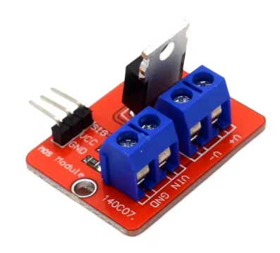
Pinout & Interface Guide
The module has two distinct sides: the low-voltage logic side (for your microcontroller) and the high-voltage load side (for your power supply and device).
Logic Side (3-Pin Header)
-
SIG (Signal): This is the control pin. Connect it to a digital or PWM-capable pin on your microcontroller. A HIGH signal (3.3V-5V) turns the MOSFET ON. A LOW signal (0V) turns it OFF. Sending a PWM signal here allows for speed/dimming control .
-
VCC (+5V): This powers the module’s internal circuitry and the status LED. Connect to your microcontroller’s 3.3V or 5V output pin .
-
GND (Ground): This is the common ground. It is crucial to connect this pin to the ground (GND) of your microcontroller and also to the ground of your high-power external supply (if one is used) to complete the circuit .
Load Side (3-Pin Screw Terminal)
-
**V+ (or + ): ** This is the positive input for the load you want to control. Connect the positive wire from your external DC power supply (e.g., a 12V battery or 24V adapter) to this terminal.
-
**V- (or – ): ** This is the negative input for the load. Connect the negative wire from your external DC power supply to this terminal.
-
**V- (or OUT – ): ** This is the switched output. Connect the negative wire of your load (motor, LED, etc.) to this terminal. The MOSFET acts as a switch between this terminal and the power supply ground. The load’s positive wire should be connected directly to the positive terminal of your external power supply.
Usage Guide
Important Safety Warnings
-
Inductive Loads: When controlling inductive loads like motors, solenoids, or relays, the module may require an external flyback diode connected in parallel with the load to protect the MOSFET from voltage spikes generated when the device is switched off. While some modules include this, verify yours. If not, add a 1N400x series or similar fast-recovery diode .
-
Heatsinking: The IRF520 can handle up to 5A, but at currents above 1A, the MOSFET will generate significant heat. For continuous operation above 1A, a heatsink is absolutely required to prevent thermal damage .
-
Power Supply Voltage: Do not exceed the maximum load voltage of 24V DC on the load side. Applying a higher voltage will permanently damage the MOSFET.
-
Logic Supply Voltage: Do not apply more than 5V to the VCC and SIG pins. This can damage the module’s internal circuitry.
Wiring Guide
This example shows how to control a 12V DC motor or LED strip with an Arduino.
Example Arduino Code
This code demonstrates both simple on/off control and PWM dimming/speed control.
int mosfetPin = 9;
int brightness = 0;
void setup() {
pinMode(mosfetPin, OUTPUT);
}
void loop() {
digitalWrite(mosfetPin, HIGH);
delay(2000);
digitalWrite(mosfetPin, LOW);
delay(2000);
for (brightness = 0; brightness <= 255; brightness++) {
analogWrite(mosfetPin, brightness);
delay(10);
}
for (brightness = 255; brightness >= 0; brightness--) {
analogWrite(mosfetPin, brightness);
delay(10);
}
delay(1000);
}
Q: What is the difference between this MOSFET module and a mechanical relay?
A MOSFET module is a solid-state switch with no moving parts. Key differences:
-
Speed: MOSFETs can switch on and off much faster than relays, enabling PWM for speed/dimming control .
-
Noise: MOSFETs operate silently, while relays produce an audible “click.”
-
Durability: No mechanical contacts to wear out, pit, or weld, making it more reliable for frequent switching.
-
Type of Control: A relay is simply an on/off switch. A MOSFET can be used for analog control (varying the power) via PWM.
Q: What types of loads can I control with this module?
You can control various DC loads up to 24V, including:
-
DC motors (for speed control)
-
High-power LED strips or single LEDs (for dimming)
-
Solenoid valves
-
Water and air pumps
-
Relay modules (to control even higher power)
-
Other DC-powered actuators
Q: Can this module control AC loads (like a household light)?
No, absolutely not. The IRF520 is a DC-specific component. It is designed to switch DC voltage only. Attempting to control AC mains voltage (e.g., 110V or 220V AC) with this module is extremely dangerous and will destroy the module instantly.
Q: Can I use this module with a 3.3V logic controller like a Raspberry Pi or ESP32?
Yes. The SIG and VCC pins accept 3.3V logic levels, making it directly compatible with these controllers
Q: What power supply should I use for the load?
The load power supply voltage must be within 0V to 24V DC. Its current rating should be at least as high as the maximum current your load will draw (e.g., use a 5A supply for a 4A motor)
Q: Do I need a heatsink?
It depends on your current.
-
Below 1A: Typically, no heatsink is needed for intermittent use.
-
Above 1A: A heatsink is highly recommended for continuous operation. At currents approaching 5A, a good heatsink is mandatory to prevent the MOSFET from overheating and being damaged
Q: The module gets hot. Is this normal?
Some warmth is normal, especially at higher currents. The IRF520 has an on-resistance of about 0.27Ω . At 2A, it will dissipate about P = I² * R = (2²) * 0.27 = 1.08 Watts, which will cause noticeable heat. If it’s too hot to touch (>60°C), you need a heatsink or better airflow.
Q: My motor runs at full speed, but I can't slow it down with PWM.
This is often a frequency issue. Try lowering the PWM frequency in your code. Many motor drivers expect frequencies in the range of a few hundred Hz to a few kHz. Some microcontrollers default to very high frequencies (e.g., 1kHz+), which might not work well with the motor’s inductance.
Q: The status LED lights up, but my load doesn't turn on. What's wrong?
Check these common issues:
-
Wiring: Double-check all connections on the load side. Remember the MOSFET switches the ground (negative) side of the circuit. The load’s positive must go to the power supply positive, and the load’s negative to the module’s OUT terminal.
-
Ground Loop: Ensure that the GND of your microcontroller is connected to the GND of the module and that the GND of your external power supply is also connected to the module’s GND (often through the power supply’s negative terminal). All grounds must be common .
-
Power Supply: Verify that your external power supply is turned on and outputting the correct voltage.
Q: Do I need to use the external power supply (V+ and V- terminals) if my load is only 5V?
You can power a 5V load directly from your microcontroller’s 5V pin, but only if the current draw is very low (e.g., a single small LED). For any motor or high-power LED, you must use an external 5V power supply connected to the V+ and V- terminals. Powering a motor directly from your Arduino’s 5V pin can damage your Arduino.
Q: What is a flyback diode and do I need one?
A flyback diode is a protection diode placed across an inductive load (like a motor, solenoid, or relay coil). When power to an inductive load is switched off, it generates a high-voltage spike in the opposite direction, which can destroy the MOSFET . If your module does not have one pre-installed, you should add a 1N400x or similar diode across the motor’s terminals (with the cathode/banded end connected to the motor’s positive supply).
Q: The load stays on even when the SIG pin is set to LOW.
This indicates the MOSFET is not fully turning off. The most common cause is that the gate charge is not being drained. Ensure that your microcontroller pin is configured as an OUTPUT and is being driven LOW (0V). A failing or incorrectly wired module could also cause this.