Product Overview
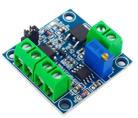
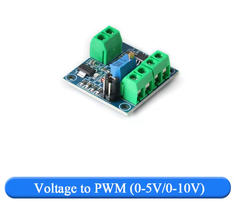
The Voltage to PWM Converter Module is an essential signal conditioning tool designed to bridge the gap between industrial analog control systems and digital microcontrollers. This module performs the reverse function of its counterpart—it takes a standard analog voltage signal (0-5V or 0-10V) and converts it into a proportional 0% to 100% duty cycle PWM (Pulse Width Modulation) signal that can be read by digital devices .
Many industrial sensors, PLCs, and process control systems output analog voltage signals, while modern microcontrollers like Arduino, ESP32, and Raspberry Pi excel at reading digital PWM signals. This module solves that interface problem. By accepting a 0-5V or 0-10V analog input from your industrial equipment, it outputs a clean, linear PWM signal that your microcontroller can easily interpret using simple digital read techniques or input capture interrupts .
This converter is the perfect tool for integrating industrial sensors and controllers into DIY and embedded projects. Its primary applications include:
-
Interfacing industrial 0-10V sensors with 5V microcontrollers .
-
Reading analog signals from PLCs using Arduino or ESP32 digital inputs .
-
Converting legacy analog control voltages for modern digital controllers .
-
Creating adjustable PWM signals for motor drivers, LED dimmers, and power supplies using a simple potentiometer .
-
Long-distance signal transmission (PWM signals are more noise-immune than analog voltage over long wires) .
With its selectable input range, adjustable output frequency, and compact design, this module provides a professional and reliable solution for translating the analog language of industry into the digital language of modern microcontrollers.
Key Features
-
Analog to PWM Conversion: Converts a 0-5V or 0-10V DC analog voltage signal into a proportional 0% to 100% duty cycle PWM digital signal, with excellent linearity and accuracy .
-
Selectable Input Range: Features onboard jumper pads or switches to select between 0-5V and 0-10V input ranges, allowing compatibility with a wide variety of industrial sensors and controllers .
-
Adjustable Output Frequency: The PWM output frequency can be configured via jumper pads or potentiometer adjustment, typically ranging from 1kHz to 20kHz or even higher on some models, allowing you to match the requirements of your receiving device .
-
Wide Power Supply Compatibility: Operates on a DC supply voltage of 5V to 30V (depending on model variant), making it easy to power from existing system rails or from your microcontroller’s power output .
-
Dual Output Drive Modes: Many versions provide both PNP (positive) and NPN (open-collector) PWM output options, allowing interface with both sinking and sourcing input circuits .
-
Onboard Calibration Potentiometer: Includes a precision trimmer potentiometer that allows you to calibrate the zero and span of the conversion, ensuring accurate mapping between input voltage and output duty cycle .
-
Phase Selection (Inverting/Non-Inverting): Some models allow you to select whether the output PWM duty cycle increases with input voltage (positive phase) or decreases (negative phase), providing flexibility for different control system requirements .
-
High PWM Resolution: Delivers linear 0% to 100% duty cycle mapping with accuracy typically within 1-5% , suitable for most industrial and hobby applications .
-
Compact and Mountable Design: Small PCB footprint with mounting holes for easy integration into control panels, enclosures, or DIN rail systems.
-
Clear Screw Terminal Connections: Features labeled screw terminals for secure and reliable connections to power, input voltage, and output PWM signal.
Technical Specifications
Pinout & Interface Guide
The module features clearly labeled screw terminals for all connections. Pin configurations may vary slightly between manufacturers; always verify the silkscreen on your specific module.
Power Supply
-
VCC / 24V / + (Power Input): Connect to the positive terminal of an external DC power supply (voltage range depends on your specific module, typically 5-24V). This powers the module’s internal circuitry .
-
GND / G / – (Power Ground): Connect to the negative terminal (ground) of the external DC power supply.
Analog Input
-
IN / VIN / SIG (Input Signal +): Connect to the positive output of your analog voltage source (0-5V or 0-10V sensor, PLC, potentiometer, etc.) .
-
GND / G (Input Signal -): Connect to the ground of your analog signal source. This is often the same as the power supply ground.
PWM Output
-
OUT / PWM (PWM Output): This is the converted PWM signal output. Connect this terminal to the digital input pin of your microcontroller or to the input of a device expecting a PWM signal .
-
GND / G (Output Ground): Connect this to the ground of the receiving device (microcontroller, etc.).
Configuration Jumpers/Pads
-
J1 / Range Select: A solder pad or jumper to select the input voltage range. Typically:
-
J2 / Frequency Select: A solder pad or jumper to select the output PWM frequency. Typically:
-
Potentiometer: A small screw-adjustable trimmer used for calibration. It adjusts the gain or offset of the conversion .
Usage Guide
Important Pre-Operation Checks
-
Power Supply: Ensure your DC power supply voltage matches the requirements of your specific module (e.g., 5-12V or 9-24V). Connect to VCC and GND terminals with correct polarity. Reverse polarity can damage the module .
-
Input Range Selection: Crucially, configure the input range jumper/pad to match your analog source. If your source outputs 0-10V, you must short the appropriate jumper. If it outputs 0-5V, leave it open . Connecting a 10V signal to a module set for 5V input may exceed the input range and cause inaccurate readings or damage.
-
Frequency Selection: Choose the PWM output frequency that best suits your receiving device. A lower frequency (1kHz) is suitable for most microcontrollers reading PWM. A higher frequency (8kHz+) may be better for driving certain motor controllers or for reduced ripple when filtering back to analog .
Calibration Procedure
For the most accurate results, calibrate the module to your specific input signal.
-
Power Up: Connect the power supply (e.g., 12V) to the module.
-
Apply Known Input: Connect a precision voltage source to the IN and GND terminals. Set it to a known mid-range value, such as 2.50V (for 0-5V mode) or 5.00V (for 0-10V mode).
-
Monitor Output: Connect an oscilloscope to the OUT and GND terminals, or use a microcontroller with a PWM input capture function to measure the duty cycle.
-
Adjust Potentiometer: Using a small screwdriver, carefully turn the calibration potentiometer on the module until the output PWM duty cycle reads exactly 50% .
-
Verify Linearity: Test at 0% input (should give 0% duty cycle) and 100% input (should give 100% duty cycle) to ensure full-scale accuracy.
Wiring Guide (Industrial 0-10V Sensor to Arduino)
This example shows how to read an industrial 0-10V pressure sensor using an Arduino’s digital pin.
Example Arduino Code (Reading PWM with PulseIn)
This code reads the PWM signal from the converter module using the pulseIn() function and calculates the corresponding input voltage.
int pwmPin = 2;
unsigned long highTime, lowTime;
float frequency, dutyCycle, inputVoltage;
int inputRange = 10;
void setup() {
pinMode(pwmPin, INPUT);
Serial.begin(9600);
Serial.println("Voltage to PWM Converter Demo");
}
void loop() {
highTime = pulseIn(pwmPin, HIGH);
lowTime = pulseIn(pwmPin, LOW);
if (highTime > 0 && lowTime > 0) {
float period = highTime + lowTime;
frequency = 1000000.0 / period;
dutyCycle = (highTime / period) * 100.0;
inputVoltage = (dutyCycle / 100.0) * inputRange;
Serial.print("Duty Cycle: ");
Serial.print(dutyCycle, 1);
Serial.print("%, Frequency: ");
Serial.print(frequency, 0);
Serial.print(" Hz, Input Voltage: ");
Serial.print(inputVoltage, 2);
Serial.println(" V");
} else {
Serial.println("No PWM signal detected");
}
delay(500);
}
Using with a Potentiometer for Manual Control
You can also use this module to generate a manually adjustable PWM signal for testing or control purposes:
-
Connect a 10kΩ potentiometer as a voltage divider:
-
As you turn the potentiometer, the input voltage varies from 0V to VCC, and the output PWM duty cycle varies correspondingly from 0% to 100%
Q: What is the main purpose of this module?
Its main purpose is to act as a translator from the analog world to the digital world. It takes a standard analog voltage signal (0-5V or 0-10V) from industrial sensors, PLCs, or manual controls and converts it into a digital PWM signal (0% to 100% duty cycle) that can be easily read by microcontrollers like Arduino, ESP32, or Raspberry Pi
Q: What is the difference between this module and the PWM to Voltage module?
They perform opposite functions:
Choose the one that matches your signal conversion needs.
Q: Can I use this module to control a motor driver or LED dimmer?
Yes, indirectly. This module outputs a PWM signal, which is exactly what many motor drivers and LED dimmers require as a control input. You would connect the OUT pin of this module to the PWM input of your motor driver or dimmer. Then, by varying the input voltage (with a potentiometer or a sensor), you control the output speed/brightness .
Q: What types of analog sources can I connect to the input?
You can connect any analog voltage source within the selected range (0-5V or 0-10V), including:
-
Industrial sensors (pressure, temperature, flow) with analog outputs .
-
PLC analog output modules .
-
Manual potentiometers (voltage dividers) .
-
Function generators and signal sources .
-
Other microcontrollers with DAC outputs.
Q: How do I select between 0-5V and 0-10V input?
Locate the solder pad or jumper labeled J1 (or similar) on the board .
-
For 0-5V input, leave the pad open (no solder bridge).
-
For 0-10V input, create a short-circuit connection by adding a drop of solder across the two pads.
Always change this setting with power OFF.
Q: How do I change the PWM output frequency?
Locate the solder pad or jumper labeled J2 (or similar) .
-
For 1kHz output (default), leave the pad open.
-
For 8kHz output (or other higher frequency), create a short-circuit connection.
Some modules may use a potentiometer for continuous frequency adjustment
Q: Do I need to calibrate the module?
For general use, it may work well enough out of the box. However, for applications requiring precise voltage-to-duty-cycle mapping, calibration is recommended. The procedure involves applying a known mid-range voltage (e.g., 2.5V for 5V mode, 5V for 10V mode) and adjusting the onboard potentiometer until the output duty cycle reads exactly 50%
Q: What do PNP and NPN output options mean?
Some modules offer both output types :
-
PNP Output: The PWM signal swings from 0V to a positive voltage (typically 5V). This is the standard “active HIGH” logic level used by most microcontrollers.
-
NPN (Open-Collector) Output: The output transistor pulls the signal to ground when active. You need an external pull-up resistor to a positive voltage (up to 30V) to create the PWM signal. This is useful for interfacing with industrial equipment that uses sinking inputs.
Q: What power supply do I need?
The required power supply voltage depends on your specific module variant. Common ranges are:
Always check the silkscreen or specifications for your module. The power supply current requirement is minimal (typically <200mA) .
Q: Can I power the module from my Arduino's 5V pin?
Yes, if your module accepts 5V power. Check the specifications. If your module requires 9-24V, you cannot power it from the Arduino’s 5V pin. In that case, use a separate power supply.
Q: What is the accuracy of the conversion?
Typical accuracy is within ±1% to ±5% of full scale . This is suitable for most control and monitoring applications. Calibration can improve accuracy for critical applications.
Q: How much current can the PWM output source/sink?
For NPN open-collector outputs, the maximum current is typically 200mA when using an external pull-up voltage . For PNP 5V outputs, the drive capability is lower (suitable for connecting to high-impedance inputs). Do not expect to drive heavy loads directly from the PWM output.
Q: The module has power, but I get no PWM output signal.
Follow this checklist:
-
Check Input Signal: Measure the voltage at the IN terminal with a multimeter. Is it within the selected range (0-5V or 0-10V)?
-
Check Range Jumper: Is the input range jumper configured correctly for your input signal voltage? .
-
Check Power Ground: Is the power supply ground connected to the module’s GND terminal?
-
Check Output with Oscilloscope: Use an oscilloscope to check for PWM activity on the OUT pin. A multimeter may not show the pulsing signal correctly.
-
Check Output Drive Type: If using NPN output, do you have an external pull-up resistor installed? .
Q: The output duty cycle is not proportional to the input voltage.
This indicates a calibration issue. Perform the calibration procedure described above to adjust the onboard potentiometer for proper 0% to 100% mapping
Q: The output duty cycle only changes over part of the input range.
The input range jumper may be set incorrectly. For example, if you have a 0-10V signal but the module is set for 0-5V input, the output will reach 100% duty cycle at 5V and remain there for inputs above 5V. Change the jumper to the correct setting .
Q: The PWM signal is noisy or unstable.
This can be caused by:
-
Electrical Noise: Ensure your input signal wires are not running parallel to high-power AC lines. Use shielded cable if necessary.
-
Unstable Power Supply: Check that your main DC power supply is stable and well-regulated.
-
Ground Loops: Ensure all grounds (power, input signal, output signal) are properly connected and referenced.