Product Overview
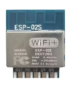
The ESP-02S Wireless WiFi Module is a compact, high-performance wireless transceiver designed for seamless integration into IoT and embedded systems. Manufactured by DOIT (Sibo Zhilian) , a trusted name in IoT modules, the ESP-02S is built around the powerful ESP8285 chip from Espressif Systems—a close relative of the legendary ESP8266 with integrated flash memory for enhanced reliability and compactness .
The ESP8285 chip features a Tensilica L106 32-bit RISC processor running at up to 160 MHz, with 16 Mbit (2 MB) of built-in flash memory. This eliminates the need for external flash chips, reducing PCB complexity and improving overall system reliability . The module supports 802.11 b/g/n Wi-Fi protocols at 2.4 GHz and includes a complete TCP/IP protocol stack, making it a complete system-on-chip (SoC) capable of running application code independently .
What sets the ESP-02S apart is its gold finger packaging—a convenient edge-connector design that allows for plug-in assembly, making it ideal for automated production and easy integration into custom PCBs . Whether you are building smart home devices, industrial IoT sensors, or wireless control systems, the ESP-02S delivers reliable performance in a compact form factor (17.3mm × 15mm) .
Key Features
-
ESP8285 Core with Integrated Flash: Powered by the ESP8285 chip featuring 16 Mbit (2 MB) of built-in flash memory , eliminating the need for external flash and improving reliability .
-
Powerful 32-bit Processor: Built around the Tensilica L106 32-bit RISC processor running at up to 160 MHz, providing ample processing power for complex IoT applications without requiring an external microcontroller .
-
Complete Wi-Fi Solution: Supports 802.11 b/g/n protocols at 2.4 GHz with integrated TR switch, balun, LNA, power amplifier, and matching network . Delivers up to 15 dBm output power with excellent receiver sensitivity down to -96 dBm .
-
Rich Peripheral Interfaces: Provides UART, HSPI, I2C, I2S, PWM, GPIO, and 10-bit ADC interfaces, allowing connection to a wide variety of sensors, actuators, and display devices .
-
Multiple Operating Modes: Supports Station (STA), SoftAP (Access Point), and SoftAP + STA modes, enabling devices to connect to existing networks or create their own .
-
Ultra-Low Power Consumption: Features multiple sleep modes with deep sleep current as low as 20 µA and standby power consumption less than 1.0 mW (DTIM3) . Wake up and transmit packets in less than 2 ms, making it ideal for battery-powered applications .
-
Gold Finger Package: The module features convenient gold finger edge connectors, allowing for easy plug-in assembly and reliable connections in production environments .
-
Smart Configuration Support: Compatible with Smart Config technology for one-click network configuration, simplifying device onboarding for Android and iOS devices .
-
Developer-Friendly: Fully supported in Arduino IDE, MicroPython, NodeMCU (Lua), and ESP-IDF. A vast online community provides extensive libraries and code examples.
-
Comprehensive Security: Supports WEP/WPA/WPA2-PSK security protocols, ensuring secure wireless communication .
Technical Specifications
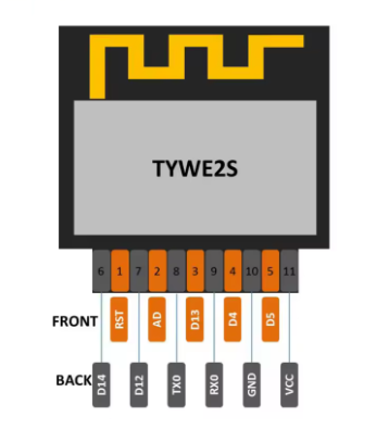
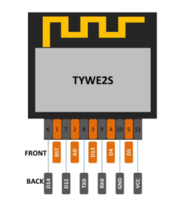
Pinout & Interface Guide
The ESP-02S features a gold finger edge connector with the following pin assignments :
Boot Mode Configuration
The ESP-02S’s boot mode is determined by the state of GPIO0, GPIO2, and GPIO15 :
Critical Notes:
-
GPIO15 must be pulled LOW during boot for both modes
-
GPIO2 must be pulled HIGH during boot
-
GPIO0 must be LOW to enter programming mode, HIGH for normal operation
Usage Guide
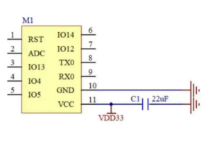
Power Supply Requirements
The ESP-02S requires a stable 3.3V DC power supply capable of providing at least 500mA during peak operation . For reliable operation:
-
Use a low-dropout regulator (LDO) such as AMS1117-3.3 with sufficient current capability
-
Do not use low-current LDOs like XC6206 or 7533—they cannot supply the required 500mA peak current
-
Add a 10µF to 100µF electrolytic capacitor and a 0.1µF ceramic capacitor close to the VCC pin for power decoupling
-
Do not apply 5V to any pin—this will permanently damage the module
-
For PCB designs, ensure power and ground traces are no less than 30 mil (0.762 mm) to handle peak currents
Programming the ESP-02S
Method 1: Using a USB-to-TTL Adapter
This is the simplest method for programming the module:
Enter Programming Mode:
-
Connect GPIO0 (pin 11) to GND
-
Connect GPIO15 (pin 9) to GND
-
Connect GPIO2 (pin 10) to VCC (pull HIGH)
-
Connect EN (pin 3) to VCC (pull HIGH)
-
Apply power or pulse RST LOW (pin 1)
-
Upload firmware via Arduino IDE or esptool
-
After upload, disconnect GPIO0 from GND and reset
Setting Up Arduino IDE for ESP-02S
-
Install ESP8266 Board Package:
-
Open Arduino IDE → File → Preferences
-
Add to “Additional Boards Manager URLs”: https://arduino.esp8266.com/stable/package_esp8266com_index.json
-
Tools → Board → Boards Manager → Search “esp8266” → Install
-
Select Board:
-
Configure Flash Settings:
AT Command Firmware
The ESP-02S typically comes pre-loaded with AT command firmware. The default baud rate is 115200 . AT commands end with a new-line (CR-LF), so serial tools should be set to “New Line Mode” .
Basic AT Command Sequence:
AT                    // Check communication
AT+GMR                // Check firmware version
AT+CWMODE=1           // Set to Station mode
AT+CWJAP="SSID","PASSWORD"  // Connect to Wi-Fi
AT+CIFSR              // Get IP address
AT+CIPSTART="TCP","192.168.1.100",80  // Open TCP connection
AT+CIPSEND=5          // Send data
> HELLO                // Data to send
Development Environments
-
Arduino IDE: User-friendly environment with extensive libraries
-
PlatformIO: Professional development environment with ESP8266 support
-
ESP-IDF: Official Espressif development framework for advanced users
-
MicroPython: Python-based development for rapid prototyping
-
NodeMCU (Lua): Lua-based firmware for quick project development
PCB Design Recommendations
For reliable operation and optimal RF performance:
-
Power traces: At least 30 mil (0.762 mm) width for power and ground
-
Vias: Use 2-3 vias on power lines to prevent PCB production deviation
-
Antenna placement: No parallel wiring near the PCB antenna
-
Download interface: Reserve pads away from the antenna for programming access
Applications
The ESP-02S is widely used in:
-
Smart Home: Smart plugs, smart LED lights, Wi-Fi detectors
-
Industrial IoT: Equipment monitoring, industrial wireless control
-
Sensor Networks: Environmental monitoring, mesh networks
-
Wireless Positioning: Location identification, beacon systems
-
Serial-to-WiFi: Transparent transmission for serial devices
Q: What is the difference between ESP-02S and ESP-01?
The ESP-02S offers several advantages:
-
Integrated flash: 2MB built-in flash (vs external flash on ESP-01)
-
Better RF performance: 15dBm output power with -96dBm sensitivity
-
Gold finger packaging: Convenient plug-in design for automated assembly
-
More GPIO pins: 10+ GPIOs available
Q: What is the difference between ESP-02S and ESP-12 series?
The ESP-02S uses the ESP8285 chip with integrated 2MB flash , while ESP-12 series typically use ESP8266 with external flash. The ESP-02S is more compact (17.3mm × 15mm) and features gold finger edge connectors for easier assembly
Q: What is the maximum range of the ESP-02S's Wi-Fi connection?
With its PCB antenna, the ESP-02S achieves ranges of up to 100-200 meters in open space. In practical indoor applications with walls and obstacles, the range is typically 30-50 meters.
Q: Does the ESP-02S support Bluetooth?
No. The ESP8285/ESP8266 series is Wi-Fi only. For Bluetooth capability, consider the ESP32 series.
Q: Can the ESP-02S operate as a standalone microcontroller?
Yes. The ESP8285 includes a 32-bit processor capable of running application code directly. You can program it with Arduino, MicroPython, or the ESP8266 SDK without requiring an external microcontroller
Q: What voltage does the ESP-02S require?
The ESP-02S requires a stable 3.3V DC power supply. The operating range is 3.0V to 3.6V . Never apply 5V to the VCC pin or any GPIO pin—this will destroy the module.
Q: How much current does the ESP-02S need?
The peak RF instantaneous current can reach 400-500mA, so the power supply must be capable of delivering at least 500mA . Low-current LDOs like XC6206 and 7533 cannot be used
Q: What size traces should I use for power and ground in my PCB?
Based on the 500mA power requirement, power and ground traces should be no less than 30 mil (0.762 mm) . If vias are used on power lines, it is recommended to make 2-3 holes to prevent PCB production deviation
Q: The module fails to start or keeps restarting. What should I check?
This is often a power supply issue. Check:
-
Power supply capability (must provide ≥500mA)
-
Power trace width (should be ≥30mil)
-
Vias on power lines (use 2-3 vias)
-
Diodes connected in series on the power supply
Q: Can I power the ESP-02S with batteries?
Yes. The ESP-02S’s low power consumption makes it suitable for battery-powered applications. A single 18650 lithium-ion cell (3.7V) can be used with a 3.3V LDO capable of providing 500mA. With proper deep sleep management, battery life of months is achievable.
Q: How do I put the ESP-02S into programming mode?
To enter programming (UART download) mode :
-
Pull GPIO0 LOW (connect to GND)
-
Pull GPIO15 LOW (connect to GND)
-
Pull GPIO2 HIGH (connect to VCC)
-
Pull EN HIGH (connect to VCC)
-
Apply power or pulse RST LOW
Q: Why can't I upload code to my ESP-02S?
Common upload issues:
-
GPIO0 not held LOW during power-on/reset
-
Incorrect serial connections (TX to RX, RX to TX)
-
Insufficient power supply (USB-to-TTL adapters may not provide enough current)
-
Wrong board selection in Arduino IDE (select “Generic ESP8266 Module”)
-
Missing pull-down on GPIO15
Q: What is the baud rate for programming and AT commands?
The default baud rate is 115200 baud . The bootloader outputs diagnostic information at 74880 baud, but for reliable programming, use 115200 baud
Q: Should I clean the module before programming?
Yes. Before downloading a program, it is recommended to wipe the module clean, otherwise there may be some failures to start
Q: Does the ESP-02S have any anti-static concerns?
The anti-static ability of ESP8285 is slightly weaker than some alternatives. In dry seasons (especially winter), pay attention to electrostatic protection during handling
Q: What is the difference between deep sleep and normal operation?
Deep sleep is an ultra-low power mode that shuts down most of the module’s functions, reducing current consumption to 20µA . The module can wake up and transmit packets in less than 2 ms, making it ideal for battery-powered applications that only need to transmit data intermittently
Q: What can I build with the ESP-02S?
Popular applications include :
-
Smart Home: Smart plugs, smart lighting control
-
Environmental Monitoring: Temperature, humidity sensors
-
Industrial IoT: Equipment monitoring, industrial wireless control
-
Wireless Positioning: Location beacons, tracking systems
-
Serial to WiFi: Transparent transmission for legacy serial devices
-
Sensor Networks: Mesh networks, data aggregation
Q: Is the ESP-02S suitable for commercial products?
Yes. The ESP-02S has passed FCC, CE, and SRRC certifications . Its gold finger packaging is designed for automated assembly, making it suitable for mass production.
Q: What firmware options are available?
Popular firmware choices include :
-
AT Command Firmware: Default firmware for co-processor mode
-
NodeMCU (Lua): Open-source Lua-based firmware for easy programming
-
MicroPython: Python-based development for rapid prototyping
-
Arduino/C++: Custom code via Arduino IDE
-
ESP-IDF: Official Espressif development framework
Q: Does the ESP-02S support OTA (Over-The-Air) updates?
Yes. The 2MB flash memory supports OTA firmware updates, allowing you to upload new code wirelessly without physically connecting to the module