Product Overview
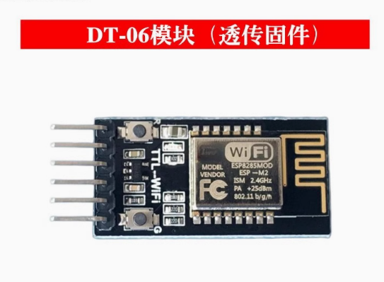
The ESP-M2 WiFi Serial Transparent Transmission Module is a compact, high-performance wireless communication solution designed to bridge the gap between serial devices and Wi-Fi networks. What sets this module apart is its 6-pin interface that is fully compatible with the popular HC-06 Bluetooth module —allowing you to instantly upgrade existing Bluetooth projects to WiFi without changing your hardware setup or code .
Built around the powerful ESP8285 chip (an enhanced version of the legendary ESP8266 with integrated flash memory), this module comes preloaded with industrial-grade transparent transmission firmware V3.0 . This means it works right out of the box: simply power it up, connect to its built-in web interface for configuration, and it will automatically forward any data received over the serial port to a Wi-Fi network (and vice versa) .
Whether you need to retrofit legacy industrial equipment with wireless monitoring, build a wireless data logger, or add cloud connectivity to your next IoT project, the ESP-M2 provides a reliable, cost-effective solution with the added benefit of seamless HC-06 compatibility.
Key Features
-
HC-06 Pin-Compatible Interface: Features a 6-pin interface that is fully compatible with the original electrical and physical interface of serial transparent Bluetooth modules (HC-06). This allows you to replace Bluetooth with WiFi without changing your PCB or wiring .
-
Preloaded Industrial-Grade Firmware: Comes with built-in serial transparent transmission firmware V3.0, which is stable, reliable, and configurable via a web browser—no programming required .
-
ESP8285 Core with Integrated Flash: Powered by the ESP8285 chip (ESP8266 with integrated 1MB flash), featuring a Tensilica L106 32-bit RISC processor running at up to 160 MHz .
-
Complete Wi-Fi Solution: Supports 802.11 b/g/n protocols at 2.4 GHz with integrated PCB antenna. Delivers up to 15dBm output power with excellent receiver sensitivity .
-
Built-in Web Configuration Server: Features an onboard HTTP web server that allows you to configure all module parameters (Wi-Fi credentials, network mode, serial settings, etc.) through a simple web browser—no additional software or apps required .
-
Multiple Operating Modes: Supports Station (STA), Access Point (AP), and Station+AP modes, enabling devices to connect to existing networks or create their own .
-
Seamless Transparent Transmission: Automatically forwards data between the serial port and a TCP/UDP connection. Once configured, the module acts as a wireless serial cable replacement .
-
Rich Network Protocols: Supports TCP Server, TCP Client, UDP Server, UDP Client, and UDP local broadcast modes, with support for DNS and automatic reconnection .
-
Ultra-Low Power Consumption: Features multiple sleep modes with deep sleep current as low as 20 µA, making it suitable for battery-powered applications .
-
Wide Operating Voltage: Accepts supply voltage from 4.5V to 6.0V (5V recommended), with TTL logic levels compatible with both 3.3V and 5V systems (5V tolerant) .
-
Industrial Temperature Range: Rated for operation from -40°C to +125°C, making it suitable for demanding industrial environments and outdoor installations .
-
State Indicator Output: Provides a dedicated STATE pin (GPIO4) that outputs a low signal when the module is successfully connected to a Wi-Fi network, with an onboard LED for visual status .
-
OTA Firmware Updates: Supports Over-The-Air (OTA) firmware updates for future upgrades .
Technical Specifications
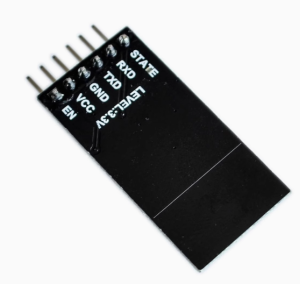
Pinout & Interface Guide
The module features a 6-pin interface that is fully compatible with HC-06 Bluetooth modules, allowing direct replacement .
Boot Mode Configuration (for Firmware Updates)
To enter programming mode for custom firmware updates:
LED Status Indicators
The onboard LED provides visual feedback of the module’s status :
Usage Guide
Getting Started
-
Power the Module: Connect a 5V DC power supply to the VCC and GND pins. The onboard LED should illuminate .
-
Connect to Your Host Device: Connect the module’s TXD pin to the RX pin of your device, and RXD to the TX pin. If your device uses 5V logic, the module’s 3.3V TTL pins are 5V tolerant .
-
Connect to the Module’s Configuration Network: By default, the module boots in AP (Access Point) mode. Use your computer or smartphone to scan for Wi-Fi networks and connect to the SSID: “Minibalance_XXXXXX” (where XXXXXX is the last six digits of the module’s MAC address). The default password is 12345678 .
-
Open the Web Configuration Page: Open a web browser and navigate to 192.168.4.1. You will see the module’s configuration interface .
-
Configure Your Settings: Use the web interface to:
-
Set the module to STA (Station) mode and enter your home Wi-Fi credentials
-
Configure the serial port settings (baud rate, data bits, parity, stop bits)
-
Set the network protocol (TCP Server, TCP Client, UDP, etc.)
-
Save the configuration
-
Start Transparent Transmission: Once configured, the module will automatically connect to your Wi-Fi network and begin forwarding data between the serial port and the network .
Web Configuration Overview
The module’s built-in web server provides several configuration pages :
Connection Diagrams
Replacing an HC-06 Bluetooth Module:
Existing HC-06 Pinout    ESP-M2 Module Pinout
   STATE      ----->        STATE
   TX         ----->        RXD
   RX         <-----        TXD
   EN/KEY     ----->        EN (optional)
   VCC        ----->        VCC (5V)
   GND        ----->        GND
Basic Connection to a Microcontroller:
ESP-M2 Module          Microcontroller (Arduino/STM32/etc.)
   TXD      ----->           RXD
   RXD      <-----           TXD
   GND      ----->           GND
   VCC      ----->           5V (external supply)
Transparent Transmission Example
Once configured as a TCP client, any data sent to the module’s serial port is automatically transmitted to the remote server, and any data received from the server is output on the serial port. This makes the module function as a wireless serial cable replacement .
AT Command Example
The module also supports standard AT commands for configuration and control at 115200 baud (default after reset):
AT                    // Check communication
AT+GMR                // Check firmware version
AT+CWMODE=1           // Set to Station mode
AT+CWJAP="SSID","PASSWORD"  // Connect to Wi-Fi
AT+CIPSTART="TCP","192.168.1.100",8080  // Open TCP connection
AT+CIPSEND=5          // Send data
> HELLO                // Data to send
Q: What is the main advantage of this module over other WiFi modules?
The key advantage is its 6-pin interface that is fully pin-compatible with HC-06 Bluetooth modules . This allows you to replace Bluetooth with WiFi in existing projects without changing your PCB layout, wiring, or host code.
Q: Do I need to write any code to use this module?
No. The module comes preloaded with industrial-grade transparent transmission firmware V3.0 . You only need to configure it via the web interface (or AT commands) to set your Wi-Fi credentials and serial parameters. After that, it automatically forwards data between your serial device and the network
Q: What types of devices can I connect to this module?
The module connects via standard UART (serial) interface. It can interface with:
-
Microcontrollers (Arduino, STM32, ESP32, etc.)
-
Industrial PLCs and controllers
-
Single-board computers (Raspberry Pi, etc.)
-
Any device with a TTL serial port
Q: Can I use this module to replace an HC-05/HC-06 Bluetooth module?
Yes. The module is fully compatible with the electrical and physical interface of serial transparent Bluetooth modules . You can directly replace an HC-06 with this module, and your host device (e.g., Arduino) can communicate with it using the same UART settings.
Q: What is the maximum range of the Wi-Fi connection?
With its PCB antenna, the module achieves ranges of up to 100-200 meters in open space. In practical indoor applications with walls and obstacles, the range is typically 30-50 meters.
Q: What voltage does the module require?
The module requires a supply voltage of 4.5V to 6.0V DC, with 5V recommended . Do not apply 3.3V directly to the VCC pin—the module has an onboard regulator that requires at least 4.5V.
Q: How much current does the module draw?
Current consumption varies by operating mode :
Q: Can I connect this module to 5V logic devices?
Yes. The TXD and RXD pins have built-in 22Ω series resistors and are 5V tolerant, allowing direct connection to 5V logic devices without level shifters
Q: Can I power the module with batteries?
Yes. The module’s deep sleep current of 20µA makes it suitable for battery-powered applications. A 5V boost converter or a 4.5-6.0V battery pack is required.
Q: How do I access the web configuration page?
By default, the module boots in AP mode with SSID “Minibalance_XXXXXX” and password 12345678. Connect to this network, then open a browser and navigate to 192.168.4.1
Q: What is the default baud rate?
The default serial baud rate is 9600 bps (factory setting). This can be changed via the web configuration interface
Q: How do I reset the module to factory defaults?
You can restore factory defaults by:
-
Using the web interface “Restore” option, or
-
Sending the AT command AT+RESTORE over the serial interface
Q: The module is not connecting to my Wi-Fi network. What should I check?
Verify the following:
-
Your Wi-Fi network operates on 2.4 GHz (5 GHz is not supported)
-
The SSID and password are entered correctly (case-sensitive)
-
Your router is not blocking new devices
-
Check the STATUS LED—if it’s blinking slowly, the module is not connected
Q: What does the STATE pin do?
The STATE pin (GPIO4) outputs a LOW signal when the module is successfully connected to a Wi-Fi network. This can be used to drive an LED or signal to your host device
Q: What can I build with this module?
Popular applications include :
-
Wireless data acquisition: Replace cables with wireless links for sensors and instruments
-
Industrial equipment retrofitting: Add Wi-Fi monitoring to legacy machinery
-
Smart home devices: Wireless control of lights, appliances, and HVAC
-
Smart car control: Remote control via Wi-Fi for robotic platforms
-
Wireless serial printers: Eliminate cables for point-of-sale or industrial printers
-
LED lighting control: Industrial and outdoor LED control systems
Q: Is the module suitable for industrial applications?
Yes. The module is rated for operation from -40°C to +125°C, making it suitable for demanding industrial environments and outdoor installations
Q: Can I update the firmware over-the-air?
Yes. The module supports OTA (Over-The-Air) firmware updates, allowing you to upgrade the firmware wirelessly without physical access
Q: Can I reprogram the module with custom firmware?
Yes. The ESP8285 is fully compatible with the ESP8266 ecosystem. You can reprogram the module using the Arduino IDE, ESP-IDF, or other development tools by putting it into programming mode (pulling GPIO0 LOW during boot)