Product Overview
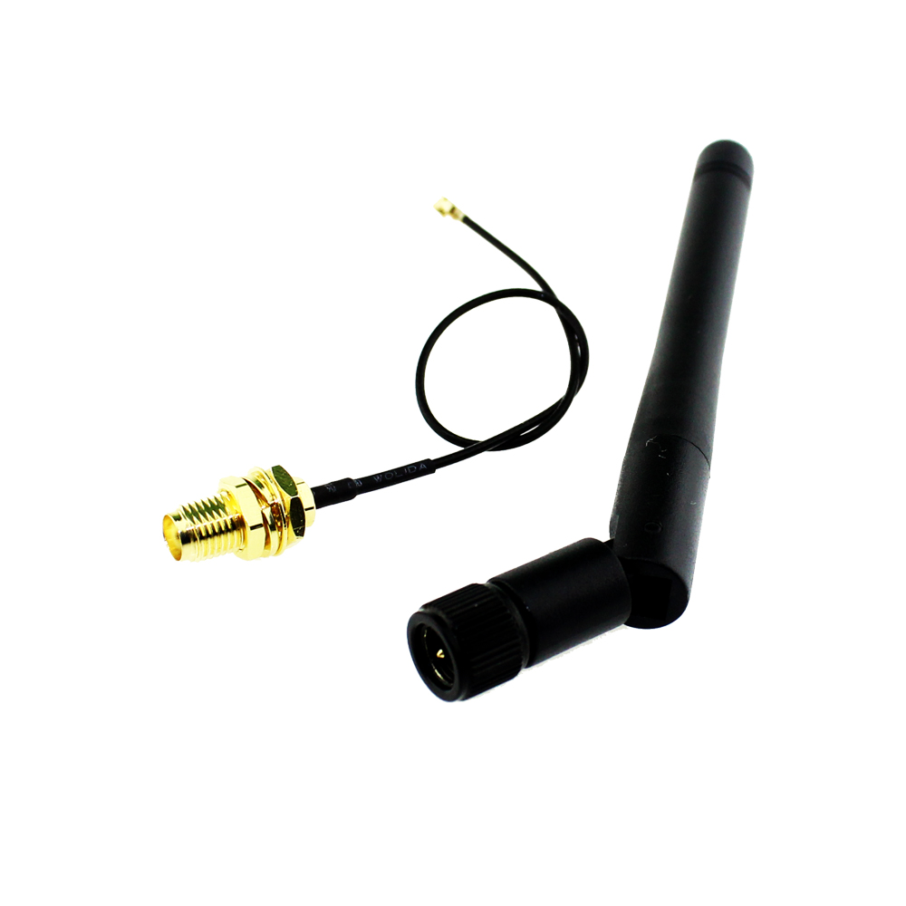
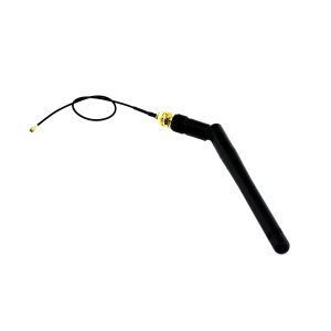
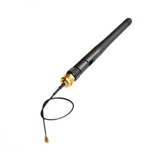
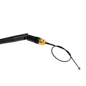
The 2.4GHz WiFi Module Antenna Extender Kit is a complete external antenna solution designed to dramatically improve the wireless range and signal stability of compatible ESP8266 modules. This kit combines a high-quality IPEX (U.FL) to SMA female adapter cable with a 3dBi gain SMA male rubber duck antenna, providing everything you need to add an external antenna to ESP-02, ESP-05, and ESP-07 modules .
Unlike ESP modules that rely solely on an onboard PCB or ceramic antenna, the ESP-02, ESP-05, and ESP-07 feature a dedicated U.FL/IPEX connector designed specifically for external antenna attachment . This kit leverages that built-in capability to replace the internal antenna with a high-performance external antenna, enabling you to:
-
Extend Wi-Fi range by 10-20 dB or more compared to the internal antenna
-
Penetrate walls and obstacles more effectively
-
Mount the antenna remotely from the ESP module for optimal placement
-
Use the module inside metal enclosures that would otherwise block the internal antenna
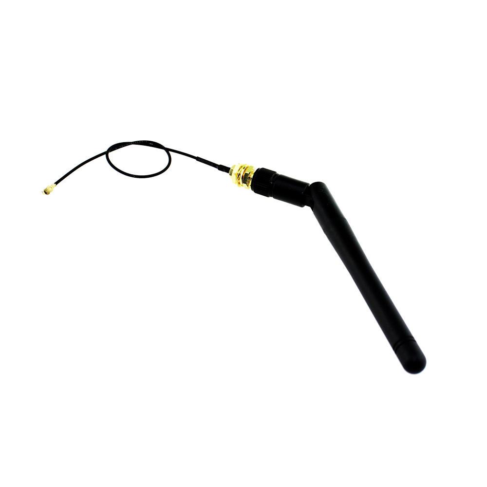
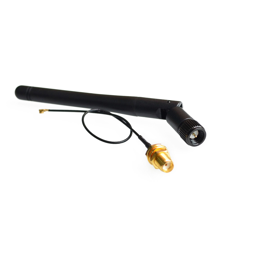
The included 3dBi gain SMA antenna provides excellent omnidirectional coverage, making it ideal for IoT sensors, smart home devices, industrial equipment, and any project where reliable Wi-Fi connectivity is critical. The flexible IPEX to SMA cable allows you to position the antenna away from the module, enabling creative enclosure designs and optimal antenna placement for maximum signal strength.
Whether you are retrofitting an existing ESP8266 project, building a device that will be installed in a challenging RF environment, or simply want the strongest possible Wi-Fi connection, this antenna extender kit delivers reliable, professional-grade performance.
Key Features
-
Complete Antenna Solution: Includes both an IPEX to SMA adapter cable and a 3dBi SMA male antenna, providing everything needed to add external antenna capability to compatible ESP8266 modules .
-
High-Gain 3dBi Antenna: The included SMA antenna delivers 3dBi gain with omnidirectional radiation pattern, significantly improving signal strength and range compared to internal PCB or ceramic antennas .
-
50-Ohm Impedance Matching: Both the cable and antenna are designed with 50-ohm impedance, ensuring optimal power transfer and minimal signal loss for maximum performance .
-
Low VSWR for High Efficiency: The antenna features a Voltage Standing Wave Ratio (VSWR) of ≤1.8, indicating excellent impedance matching and efficient power radiation .
-
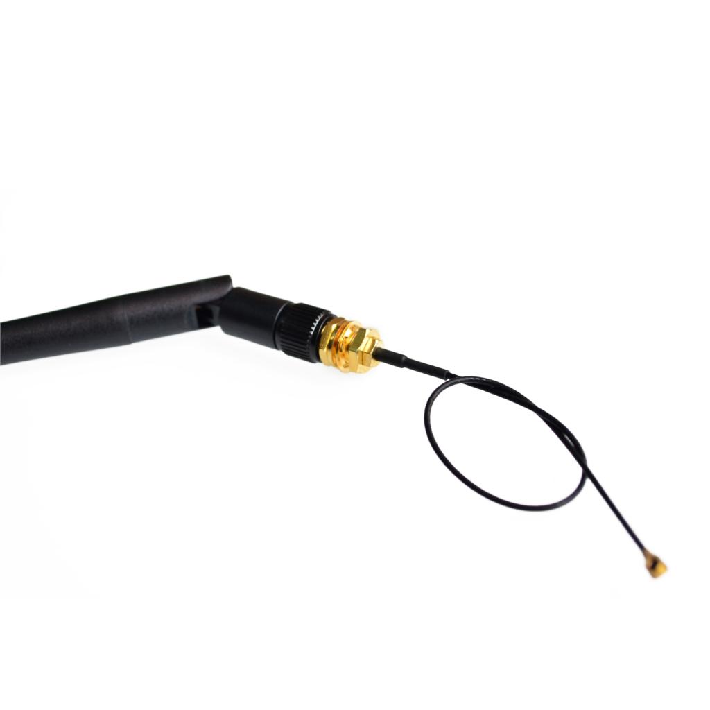
Flexible IPEX to SMA Cable: The adapter cable uses high-quality RG coaxial cable (typically RG1.13 or similar) with a U.FL/IPEX connector on one end and an SMA female connector on the other, allowing flexible antenna placement .
-
Wide Frequency Compatibility: Optimized for the 2.4 GHz ISM band (2400-2500 MHz), perfectly matched to the operating frequency of ESP8266 Wi-Fi modules .
-
Durable Construction: Features a robust antenna housing with hinged or swivel design for flexible mounting and directional adjustment. The cable is shielded for noise immunity and durability .
-
Wide Operating Temperature: Rated for operation from -40°C to +85°C, making it suitable for demanding industrial environments and outdoor installations .
-
Easy Plug-and-Play Installation: Simple to install—no soldering required. The IPEX connector snaps directly onto the module’s U.FL port, and the antenna screws onto the SMA female connector .
-
Compatible Modules: Specifically designed for ESP-02, ESP-05, and ESP-07 modules, which feature a built-in U.FL/IPEX connector for external antenna attachment .
-
Versatile Applications: Ideal for IoT sensors, smart home devices, industrial monitoring equipment, outdoor Wi-Fi projects, and any application requiring extended wireless range.
Technical Specifications
IPEX to SMA Adapter Cable
3dBi SMA Antenna
Compatibility
Pinout & Connection Guide
Connection Diagram
[ESP Module] ──┬── [IPEX Connector] ──┬── [IPEX to SMA Cable] ──┬── [SMA Female] ── [SMA Male Antenna]
               │                      │                         │
               └── (Internal Antenna) └── (External Connection) └── (Antenna Attachment)
Installation Steps
-
Locate the U.FL Connector: On the ESP-02, ESP-05, or ESP-07 module, identify the small U.FL/IPEX connector. This is typically located near the corner of the module and may be covered with a small plastic cap or unused trace .
-
Prepare for External Antenna (If Required): On some modules, the internal antenna path may need to be disabled to use the external connector. This is typically done by removing a zero-ohm resistor that connects the internal antenna to the RF output, or by cutting a trace on the PCB . Consult your specific module’s documentation before proceeding.
-
Attach the IPEX Cable: Gently snap the IPEX connector from the adapter cable onto the module’s U.FL port. The connector is small—use tweezers for precise placement. You should feel a slight click when it seats properly.
-
Route the Cable: Route the coaxial cable to your desired antenna mounting location. The flexible cable allows you to position the antenna for optimal signal.
-
Attach the Antenna: Screw the SMA male antenna onto the SMA female connector on the cable. Hand-tighten securely—do not over-tighten.
-
Mount the Antenna: Position the antenna for optimal orientation. For omnidirectional antennas, vertical orientation typically provides the best coverage .
Important: Module Compatibility Notes
Modules with Built-in External Antenna Connector:
Modules Without Built-in Connector:
-
ESP-01, ESP-12, ESP-12E, ESP-12F, NodeMCU, Wemos D1 Mini: These modules use only the onboard PCB or ceramic antenna. Adding an external antenna requires:
-
Removing the zero-ohm resistor connecting the internal antenna
-
Soldering a U.FL connector to the PCB
-
Possibly cutting the PCB trace to the internal antenna
This is an advanced modification and is not required when using ESP-02/05/07 modules.
Usage Guide
Why Use an External Antenna?
The ESP8266 modules with onboard PCB or ceramic antennas are convenient but have inherent limitations:
-
Limited range: PCB antennas typically provide only 20-50 meters in indoor environments
-
Enclosure interference: Metal enclosures completely block internal antennas
-
Environmental obstacles: Walls, floors, and other structures attenuate the signal
-
RF noise: Onboard antennas are more susceptible to interference from nearby components
An external 3dBi antenna can provide 10-20 dB of signal improvement, effectively doubling or tripling your wireless range and dramatically improving link stability .
Installation Scenarios
Scenario 1: Remote Antenna Placement
Place the ESP module inside an enclosure (such as a weatherproof box) and mount the antenna externally. This is ideal for outdoor sensors, weather stations, and industrial equipment where the module must be protected but the antenna needs clear line-of-sight.
Scenario 2: Extended Range Application
Mount the antenna in a high, unobstructed location away from the ESP module. The flexible cable allows you to position the antenna for optimal signal while keeping the module accessible.
Scenario 3: Metal Enclosure Integration
If your project requires a metal enclosure, the internal antenna would be completely blocked. With this kit, the IPEX cable allows the antenna to be mounted externally while the module remains safely inside.
Expected Performance Improvement
Based on user experience reports, adding an external antenna to compatible ESP modules can yield:
-
Signal strength improvement: 10-20 dB increase in RSSI
-
Range extension: From 20-50 meters to 100-200 meters in open space
-
Stability: Reduced packet loss and fewer connection drops
-
Penetration: Improved ability to connect through walls and obstacles
Note: Actual results vary based on environment, antenna placement, and module quality.
ESP-07 Usage Note
The ESP-07 module features both an onboard ceramic antenna and a U.FL connector. By default, the module may use the ceramic antenna. To use the external antenna, you typically need to:
-
Remove the zero-ohm resistor that connects the ceramic antenna path
-
Solder the zero-ohm resistor to the path that connects to the U.FL connector
-
Alternatively, some modules have a solder bridge selection for antenna source
Consult the ESP-07 documentation for your specific module version.
Q: Which ESP8266 modules are compatible with this antenna kit?
This kit is specifically designed for modules that have a built-in U.FL/IPEX connector for external antenna attachment, including:
Q: Can I use this antenna with ESP-01, ESP-12, or NodeMCU boards?
Not directly. These modules do not have a built-in U.FL connector. While you can modify them by soldering a U.FL connector and disabling the internal antenna, this requires advanced soldering skills and is not recommended for beginners . The ESP-02/05/07 modules are the correct choice for easy external antenna attachment.
Q: What is the difference between this kit and using just the cable or just the antenna?
This kit provides a complete solution:
-
The IPEX to SMA cable allows you to connect the module to an external SMA antenna
-
The 3dBi SMA antenna provides the actual RF radiation element
-
Using both together is required to add external antenna capability to your module
Q: What is the gain of the included antenna?
The included antenna provides 3 dBi gain, which offers a significant improvement over internal PCB antennas (typically 1-2 dBi). Higher gain antennas (5-8 dBi) are available but are larger and may have more directional radiation patterns
Q: Does the ESP-07 use the ceramic antenna or the U.FL connector?
The ESP-07 features both an onboard ceramic antenna and a U.FL connector for external antenna. By default, the module may use the ceramic antenna. To use the external connector, you typically need to modify the antenna path selection (usually by moving a zero-ohm resistor) . Consult your ESP-07 documentation for specific instructions.
Q: How much improvement can I expect from adding this external antenna?
Users report 10-20 dB improvement in signal strength (RSSI) after adding an external antenna . A 3 dB improvement represents a doubling of signal power. This typically translates to significantly extended range, improved wall penetration, and more stable connections.
Q: Does the antenna need to be in a specific orientation?
This is an omnidirectional antenna with vertical polarization . For best performance, mount the antenna vertically (pointing up or down). The hinged design allows you to adjust the angle for optimal placement
Q: Do I need to disable the internal antenna to use the external one?
On modules that have both an internal antenna and a U.FL connector (like ESP-07), you typically need to select the antenna path by moving a zero-ohm resistor or cutting a trace . On modules that only have the U.FL connector (ESP-02, ESP-05), the external antenna is the only option.
Q: Can the IPEX cable be extended further?
The included cable is typically 100-200mm long. Using longer cables can introduce additional signal loss. For applications requiring longer distances, use high-quality low-loss coaxial cable (such as RG178 or RG316) and ensure SMA-to-SMA extension cables maintain 50-ohm impedance.
Q: Is soldering required to install this kit?
No soldering is required for modules that have a U.FL connector. The IPEX connector snaps directly onto the module’s U.FL port . However, some ESP-07 modules may require moving a zero-ohm resistor to select the antenna path—this does require soldering.
Q: Will this antenna work if I mount the ESP module inside a metal enclosure?
Yes, that is one of the primary use cases. The IPEX cable allows you to keep the module inside the metal enclosure while mounting the antenna externally, completely bypassing the RF shielding effect of the enclosure
Q: I attached the antenna but my signal didn't improve. What went wrong?
Several possible issues:
-
The module may still be using the internal antenna (if it has both). Check the antenna path selection .
-
The IPEX connector may not be fully seated—ensure you hear a click when attaching .
-
The module may have been damaged during installation (IPEX connectors are delicate) .
-
Your location may have physical limitations that the antenna cannot overcome (very long distance, thick concrete walls, etc.).
Q: My ESP-07's signal is worse after adding the antenna. Why?
This likely indicates that the antenna path is not correctly selected. If the module is still connected to the internal ceramic antenna while the external antenna is attached, the external antenna may be acting as a passive radiator and detuning the internal antenna. Ensure the correct antenna path is selected (typically by moving a zero-ohm resistor) .
Q: The IPEX connector is very small. How do I attach it without damaging it?
Use fine-tipped tweezers to carefully align the connector with the module’s U.FL port. Press straight down gently—you should feel a slight click when it seats. Do not use excessive force or try to pry the connector
Q: Can I use this antenna with other 2.4 GHz devices?
Yes. This antenna kit can be used with any 2.4 GHz device that has a compatible U.FL connector and SMA interface, including Zigbee, Bluetooth, and other Wi-Fi modules. The 50-ohm impedance and 2.4 GHz frequency range make it versatile for many wireless applications
Q: What projects are ideal for this antenna kit?
This kit is perfect for:
-
Outdoor weather stations and environmental sensors
-
Industrial IoT equipment mounted in metal enclosures
-
Smart home devices located far from the router
-
Wireless sensor networks requiring extended range
-
Projects where the ESP module must be concealed while the antenna is exposed
Q: Will this antenna work for 5 GHz Wi-Fi?
No. This antenna is designed for the 2.4 GHz band (2400-2500 MHz) and will not perform correctly at 5 GHz
Q: Can I use a higher gain antenna (5-8 dBi) with this cable?
Yes. The IPEX to SMA cable is compatible with any 50-ohm SMA antenna designed for 2.4 GHz. Higher gain antennas typically have more directional radiation patterns and larger physical size, but can provide even greater range in specific directions