Product Overview
The 2262/2272 Quad Channel Wireless Remote Control is a professional-grade, ready-to-use RF control system built around the industry-standard PT2262 encoder and PT2272-M4 decoder ICs from Princeton Technology . This 4-channel wireless solution provides a simple, reliable way to add remote control capabilities to your projects without any programming or microcontroller knowledge.
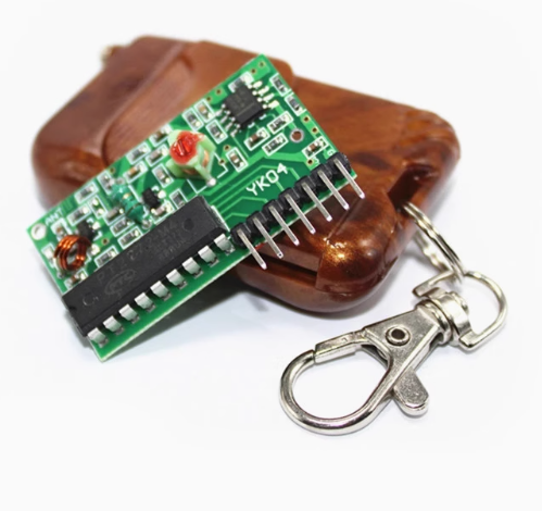
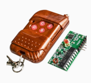
The system consists of a 4-button transmitter and a receiver board that provides four independent momentary TTL outputs (D0-D3). When you press a button on the remote, the corresponding output pin on the receiver goes HIGH for the duration of the button press—just like a wireless push button . The receiver features a VT (Valid Transmission) LED that lights up whenever a valid signal is received, providing visual confirmation of successful communication.
The PT2262/2272 chipset uses 8 tri-state address pins, offering 6561 unique address combinations . This allows multiple remote systems to operate in the same location without interference—simply set the address jumpers differently on each pair. The system operates in the license-free 315MHz or 433MHz ISM band and provides reliable wireless control up to 100 meters in open space .
Whether you are building garage door openers, home automation systems, industrial machinery controls, or wireless robotics, this 4-channel remote control kit offers a complete, plug-and-play solution that requires no programming, no Arduino, and no complex setup—just simple wiring and you’re ready to go.
Key Features
-
4 Independent Channels: Control up to four different devices or functions with a single remote. Each button corresponds to one of four outputs (D0-D3) on the receiver board
-
Momentary (M4) Output Type: All outputs are momentary—they remain HIGH only while the corresponding button is pressed and return LOW when released. This is ideal for motor control, garage doors, and applications requiring “push-button” behavior
-
TTL Compatible Outputs: The four outputs provide standard 5V TTL logic levels (0V/5V), making them directly compatible with microcontrollers, relays, and other digital circuits
-
6561 Addressable Combinations: Features 8 tri-state address pins (High, Low, or Floating) providing 3⁸ = 6561 unique address codes, allowing multiple systems to coexist without interference
-
VT Valid Transmission Indicator: Includes a dedicated VT output and LED that goes HIGH whenever a valid, correctly addressed signal is received—perfect for system status monitoring
-
ASK Modulation: Uses Amplitude Shift Keying (ASK) modulation with a 315MHz or 433.92MHz carrier frequency, offering excellent noise immunity and reliable operation
-
Wide Operating Voltage: Transmitter operates from 5V to 12V DC (23A 12V battery included); receiver operates on 5V DC
-
No Programming Required: The system uses hardware-based address encoding and decoding—no software, no microcontroller, no coding needed
Technical Specifications
Pinout & Interface Guide
Receiver Pin Assignment
Address Setting Jumpers (J1-J8)
Both the transmitter and receiver have 8 address pins that must be set identically for communication to work . Each pin can be configured in one of three states:
Important: The default configuration for most pre-assembled modules is often “all floating” (no jumpers connected). To use multiple systems, set unique address combinations on each pair .
Usage Guide
Wiring Instructions
IMPORTANT: Always disconnect power before wiring.
-
Connect Receiver Power: Connect a stable 5V DC power supply to the VCC and GND pins of the receiver board. The receiver’s operating voltage is 5V only—do not exceed this .
-
Connect Outputs: The four outputs (D0-D3) provide 5V TTL signals. Connect them to:
-
Microcontroller input pins (e.g., Arduino digital inputs)
-
Relay driver circuits (to control high-power devices)
-
LEDs for visual indication
-
Logic gates or other digital circuits
-
Monitor VT Output: The VT pin goes HIGH whenever a valid, correctly addressed signal is received. This can be used to trigger confirmation LEDs or for system status monitoring .
-
Insert Battery: The transmitter uses a 23A 12V battery (included). Insert the battery with correct polarity as marked on the remote .
Setting the Address
-
Check Default Address: Before use, verify that the address pins on both the transmitter and receiver are set identically. Many modules come with all pins floating by default .
-
Set Address Jumper: To set a pin to HIGH, connect it to VCC. To set it to LOW, connect it to GND. To leave it floating, make no connection .
-
Match Both Ends: Ensure the transmitter’s address configuration matches the receiver’s exactly. Communication will only occur when the addresses are identical .
Testing Operation
-
Power Up: Apply 5V power to the receiver. The receiver’s power LED should illuminate.
-
Press a Button: Press button A on the remote. The corresponding D0 output should go HIGH, and the VT LED should light up.
-
Verify Momentary Action: The D0 output should remain HIGH only while the button is held down. When released, it should return LOW .
-
Test All Channels: Repeat for buttons B, C, and D to confirm all four channels are working.
Range Considerations
-
Open Area: Up to 100-150 meters
-
Indoor: 5-30 meters depending on walls and obstacles
-
Antenna: For best range, ensure the antenna wire is extended straight (not coiled or cut short)
Q: What is the difference between the M4, L4, and other PT2272 versions?
The M4 version provides momentary outputs (output HIGH only while button is pressed). L4 provides latching outputs (output toggles and stays latched until next press). T4 provides toggle outputs. The PT2272-M4 is designed for applications requiring “push-button” behavior
Q: Can I use this system without a microcontroller?
Yes. The outputs are standard 5V TTL signals that can directly drive LEDs, relays (via transistor drivers), or be connected to logic gates. No programming or microcontroller is required
Q: What is the maximum range?
In open outdoor space, the range can reach 100-150 meters . Indoors, through walls and floors, the effective range is typically 5-30 meters, depending on building materials (concrete/metal reduce range).
Q: Can multiple remote systems operate in the same location without interference?
Yes. The system uses 8 tri-state address pins offering 6561 unique address combinations. By setting different address configurations on each system, multiple remotes can operate simultaneously without interference
Q: Can I use a 12V power supply with the receiver?
No. The receiver is designed for 5V DC only. Applying 12V will permanently damage the receiver. The transmitter operates on 12V (via the included 23A battery), but the receiver requires a regulated 5V supply
Q: The remote stopped working after I changed the battery. What should I do?
Check the address settings. Changing the battery does not affect the address, but ensure the battery is inserted with correct polarity. Also verify that the receiver’s address pins still match the transmitter’s configuration
Q: The receiver clicks (VT LED flashes) but my output device doesn't turn on. What's wrong?
This indicates the receiver is receiving a signal but the address may not be matching. Check that the address jumpers on both the transmitter and receiver are set identically . Also ensure your output device is connected correctly (D0-D3 are outputs, not inputs).
Q: Can I press multiple buttons at the same time?
The PT2262/2272 chipset does not support simultaneous button presses. When multiple buttons are pressed, the data output may be unreliable or only one channel may activate . For applications requiring multiple simultaneous outputs, consider using multiple remote systems or a microcontroller-based solution.
Q: How do I set the address to something other than the default?
The 8 address pins (J1-J8) can be configured in three states: High (connect to VCC), Low (connect to GND), or Floating (leave unconnected). Set the same configuration on both the transmitter and receiver for successful communication
Q: The range is very short. What can I do to improve it?
Several factors affect range:
-
Ensure the antenna wire is fully extended and straight (not coiled or cut short)
-
Avoid mounting the receiver inside metal enclosures
-
Check the transmitter battery strength (replace with fresh 23A 12V battery)
-
Reduce obstacles between the transmitter and receiver
-
Use a higher-quality external antenna on the receiver
Q: What is the VT pin used for?
The VT (Valid Transmission) pin goes HIGH whenever the receiver successfully receives and decodes a valid signal with matching address. This can be used to drive a “signal received” LED or to trigger confirmation logic in your application
Q: What can I build with this 4-channel remote control?
Popular applications include:
-
Garage door openers (using momentary mode with a relay)
-
Wireless lighting control (4 independent lights or zones)
-
Industrial machinery remote start/stop
-
Home automation and security systems
-
Wireless robotics control (4 functions or directions)
-
Remote fan or pump control
-
Automated gate control
Q: Can I use this to control a garage door opener?
Yes. Connect the receiver’s output to a relay that simulates the garage door button press. The momentary output of the PT2272-M4 is perfect for this application—the output stays HIGH only while the button is pressed, just like a physical push button.
Q: How do I control high-power devices (like motors or lights) with this system?
The outputs are 5V TTL signals (up to ~10mA). To control high-power devices, use the outputs to drive relay modules, MOSFET switches, or optocouplers that can handle higher voltages and currents.
Q: Is this system compatible with 433MHz remotes from other manufacturers?
Possibly, but not guaranteed. The PT2272-M4 can receive any 315MHz/433MHz ASK-modulated signal that matches its address configuration. However, if the remote uses a different encoding protocol or rolling code (hopping code), it will not be compatible . For reliable operation, use the matched transmitter included with the receiver.
Q: Can I use this system with a microcontroller like Arduino or ESP32?
Yes. The 5V TTL outputs can be directly connected to digital input pins on microcontrollers. The VT pin can be used as an interrupt to detect when a signal is received, allowing the microcontroller to read which output(s) are active