Product Overview
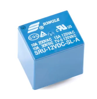
The SRD-12VDC-SL-A is a high-quality, subminiature electromagnetic relay manufactured by Songle Relay (Ningbo Songle Relay Co., Ltd.), one of the most trusted names in the relay industry . This 4-pin, 1 Form A (SPST-NO) relay is designed to switch loads up to 10A at 250V AC or 30V DC, making it an ideal choice for a wide range of applications including home appliances, office equipment, industrial control circuits, and automotive electronics .
With a 12V DC coil, this relay is perfectly suited for 12V automotive systems, industrial control panels, and various battery-powered applications. The relay features a sealed construction that protects the internal contacts from dust, humidity, and environmental contaminants, ensuring long-term reliability even in demanding conditions. It is recognized by major safety agencies, providing confidence for both hobbyist and commercial applications.
The SRD series relay employs a simple magnetic circuit design that enables high-density PCB mounting while maintaining a compact footprint. Its SPST-NO (Single Pole Single Throw, Normally Open) configuration provides straightforward ON/OFF control, making it ideal for applications where the load should be OFF by default and turned ON when the relay is activated .
Key Features
-
SPST-NO Contact Configuration (1 Form A): Single Pole Single Throw, Normally Open contact configuration with 4 pins—simple ON/OFF control
-
10A High Switching Capacity: Contacts rated for 10A at 250V AC or 10A at 30V DC, with maximum switching current up to 15A, suitable for controlling lights, fans, pumps, and small motors
-
12V DC Coil Voltage: Standard operating voltage of 12V DC with a coil resistance of approximately 400Ω and power consumption of 360mW (0.36W)
-
Compact Subminiature Design: Small footprint measuring approximately 19.2mm × 15.6mm × 15.8mm, ideal for high-density PCB mounting
-
Sealed Construction: Protects internal contacts from dust, moisture, and environmental contaminants for enhanced reliability
-
Fast Switching Time: Typical operate and release time of ≤10ms, suitable for most control applications
-
Wide Operating Temperature: Rated for operation from -40°C to +85°C, suitable for demanding environments
-
High Insulation Resistance: Insulation resistance of 100MΩ minimum at 500VDC, with dielectric strength of 1500VAC between coil and contacts
Technical Specifications
Pinout & Interface Guide
The SRD-12VDC-SL-A features 4 pins arranged in a standard configuration :
Wiring Diagram
[Coil Connection]              [Switch Contacts]
    +  ----------
     |                         COM ---o
    [Relay Coil]               NO  ---o (Open when relay OFF)
     |                         (Closed when relay ON)
    -  ----------
Contact State Summary
Usage Guide
Driving the Relay
The SRD-12VDC-SL-A requires approximately 30mA of current to energize the coil (calculated from I = V/R = 12V / 400Ω) . While this is within the capability of many transistors and relay driver ICs, it should not be driven directly by most microcontroller pins (which typically provide 20mA–40mA). A transistor driver circuit is recommended for reliable operation.
Recommended Driver Circuit (with NPN Transistor)
    +12V --------[Relay Coil]----+----- +5V/+3.3V (for logic)
                                  |
                                  |/ C
                     MCU Pin ----|  2N2222 or BC547
                                  |\ E
                                  |
                                GND

                   [Flyback Diode] (1N4148 or 1N4007)
                        +----|<|----+
                        |           |
                  [Relay Coil]       |
                        |           |
                      GND           |
                        +-----------+
Driver Circuit with MOSFET
For lower power consumption and faster switching, a logic-level N-channel MOSFET (such as BS170 or 2N7000) can be used with a gate resistor.
Basic Arduino Control Example
const int relayPin = 7;
void setup() {
pinMode(relayPin, OUTPUT);
digitalWrite(relayPin, LOW);
}
void loop() {
digitalWrite(relayPin, HIGH);
delay(5000);
digitalWrite(relayPin, LOW);
delay(5000);
}
ESP32 / ESP8266 Control Example
Since ESP32 and ESP8266 operate at 3.3V logic, they can control the transistor base directly, but the relay coil requires a separate 12V supply.
const int relayPin = 5;
void setup() {
pinMode(relayPin, OUTPUT);
digitalWrite(relayPin, LOW);
}
void loop() {
digitalWrite(relayPin, HIGH);
delay(5000);
digitalWrite(relayPin, LOW);
delay(5000);
}
Load Connection Guidelines
For AC Loads (e.g., lights, fans):
-
Connect the Live (L) wire to the COM terminal
-
Connect the Load to the NO terminal
-
Connect the Neutral (N) wire directly to the load’s neutral
For DC Loads (e.g., motors, solenoids):
-
Connect the positive (+) supply to the COM terminal
-
Connect the load’s positive wire to the NO terminal
-
Connect the load’s negative wire directly to the power supply ground
Important: Flyback Diode
Always use a flyback diode (1N4148, 1N4007, or similar) across the relay coil terminals . When the coil is de-energized, it generates a high-voltage inductive kickback that can damage the transistor or microcontroller. The diode should be placed with the cathode (banded end) towards the positive supply and the anode towards the transistor collector.
PCB Layout Considerations
-
Ensure adequate trace width for 10A switching current (recommended ≥ 2mm for 1oz copper)
-
Keep high-current traces away from sensitive signal traces
-
Provide proper clearance between coil and contact traces for safety (≥ 3mm for 250V AC)
Q: What is the difference between SRD-12VDC-SL-A and SRD-12VDC-SL-C?
The SRD-12VDC-SL-A is a 4-pin SPST-NO (Single Pole Single Throw, Normally Open) relay with only COM and NO contacts . The SRD-12VDC-SL-C is a 5-pin SPDT (Single Pole Double Throw) relay with COM, NO, and NC contacts . Choose the A version for simple ON/OFF control; choose the C version if you need both NO and NC switching options.
Q: What is the maximum load this relay can handle?
The contacts are rated for 10A at 250V AC (resistive) or 10A at 30V DC . The maximum switching current can reach 15A under specific conditions . For inductive loads like motors or solenoids, it is recommended to derate to 5A–7A to account for startup surges.
Q: Can I use this relay directly with an Arduino, ESP32, or ESP8266?
The relay coil draws approximately 30mA at 12V . While this is lower than the 5V versions, most microcontroller pins cannot directly supply 12V. A transistor driver circuit is required to interface the 12V relay coil with a microcontroller. ESP32 and ESP8266 (3.3V logic) can control the transistor driver directly, but the relay coil requires a separate 12V supply.
Q: What is the purpose of the flyback diode?
When the relay coil is de-energized, it generates a high-voltage inductive kickback that can destroy the transistor or microcontroller . A flyback diode (1N4148, 1N4007) placed across the coil protects the driver circuit by providing a safe path for this energy to recirculate.
Q: What is the difference between Form A and Form C contacts?
Form A (1 Form A) is SPST-NO (Single Pole Single Throw, Normally Open) —the contacts are open when the relay is de-energized . Form C (1 Form C) is SPDT (Single Pole Double Throw) —provides both NO and NC contacts for more flexible switching .
Q: What is the coil resistance of this relay?
The SRD-12VDC-SL-A has a coil resistance of 400Ω ± 10% . This determines the current draw: I = V / R = 12V / 400Ω = 30mA
Q: What is the minimum voltage required to activate the relay?
The pick-up (pull-in) voltage is ≤ 75% of nominal voltage, meaning the relay will reliably activate when the coil voltage reaches 9V or higher. For consistent operation, it is recommended to use the full 12V.
Q: What is the expected lifespan of this relay?
The relay is rated for 10 million mechanical operations (no load) and 100,000 electrical operations at the rated load . Actual lifespan depends on switching frequency and load type.
Q: Does the relay require a heatsink?
No. The relay is designed for PCB mounting with natural cooling. At 10A continuous load, the contacts may warm slightly, but no additional heatsink is required.
Q: Can I use this relay for 220V AC applications?
Yes. The contacts are rated for 10A at 250V AC, which is suitable for 220V/240V systems . Ensure proper insulation and clearance between coil and contact pins for safety.
Q: The relay clicks but my load doesn't turn on. What's wrong?
This indicates the coil is energizing but the load circuit is incomplete. Check:
-
The load’s wiring (COM to power source, NO to load)
-
The load’s neutral/ground is connected correctly
-
The load itself is functional
-
Contact continuity with a multimeter (should show closed when coil energized)
Q: The relay chatters or buzzes. What causes this?
Chatter usually indicates:
-
Insufficient coil voltage (below 9V)
-
Unstable power supply
-
Insufficient driver current
-
Loose connections
-
Contact contamination from switching inductive loads without proper suppression
Q: Can I use this relay in high-vibration environments?
The relay is designed for standard industrial environments. For extreme vibration applications, consider using a relay with additional mechanical reinforcement or a solid-state relay (SSR).
Q: What can I build with the SRD-12VDC-SL-A relay?
Popular applications include :
-
Automotive systems: 12V lighting, window controls, power locks
-
Industrial control: PLC outputs, motor control, conveyor systems
-
Home automation: Lighting control, appliance switching
-
Security systems: Alarm triggers, access control
-
HVAC systems: Fan control, thermostat switching
-
Solar power systems: Battery switching, panel control
Q: Can I use this relay with a 12V automotive battery?
Yes. The 12V coil voltage is perfectly suited for automotive applications. Ensure the relay is protected from moisture and vibration when installed in vehicles.
Q: Is this relay suitable for controlling a pump or motor?
Yes, with derating. For inductive loads like motors, it is recommended to operate at 50–70% of the rated contact current (5A–7A) to account for startup surges. Consider adding a snubber circuit (RC network) across the contacts to suppress arcing.
Q: Can I use multiple relays together?
Yes. Multiple SRD-12VDC-SL-A relays can be used in parallel to control multiple loads. Ensure your power supply can handle the combined coil current (30mA per relay plus load currents). Use separate transistor drivers for each relay to avoid overloading a single microcontroller pin.