Product Description
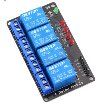
The 12V 4-Way Electromagnetic Relay Module is a robust and versatile switching interface designed for 12V control systems commonly found in automotive, marine, industrial, and off-grid solar applications. Operating on a straightforward low-level trigger logic, it provides a seamless interface between 12V microcontroller outputs, PLCs, or switch panels and high-power AC/DC loads. The module’s design emphasizes durability and clarity, featuring bright status LEDs for each channel and secure screw terminals for reliable electrical connections.
This non-optocoupler module utilizes a direct-drive circuit, offering a cost-effective and responsive solution for environments where a common 12V power system is already established. Each of the four channels is controlled by a high-quality electromagnetic relay capable of switching substantial currents. Its construction makes it ideal for applications that demand consistent performance in varying conditions, from vehicle installations to control cabinets, providing a dependable link between low-voltage logic and high-power devices.
Key Features
-
12V System Compatibility: Designed for direct integration into 12V DC systems, common in vehicles, boats, and industrial control panels.
-
Low-Level Trigger Logic: The relay activates when the control signal is pulled to ground (LOW), which is intuitive for most microcontroller and switch interfaces.
-
Four Independent High-Current Channels: Control up to four separate circuits, with each relay capable of switching significant loads.
-
Clear Operational Feedback: Each channel includes a bright status LED that illuminates when the relay is energized, providing instant visual confirmation.
-
High-Power Relay Contacts: Industrial-grade relays with SPDT (Single Pole Double Throw) contacts allow switching of both AC and DC loads.
-
Non-Optocoupler Design: A simplified, efficient circuit for direct control within a shared 12V power environment, ensuring fast response.
-
Secure Screw Terminals: Robust terminals for both the 12V control power and the high-current load wiring, preventing loose connections.
-
Wide-Range Application: Perfect for 12V-based projects, from automotive automation to renewable energy system control.
Main Parameters
-
Number of Channels: 4
-
Trigger Logic: Low Level (Active LOW)
-
Control Signal Voltage: 12V DC (compatible with 10-15V logic)
-
Module Operating Voltage: 12V DC
-
Relay Contact Rating: 10A @ 250VAC / 10A @ 30VDC
-
Relay Type: Electromagnetic, Single Coil
-
Contact Configuration: SPDT (COM, NO, NC)
-
Dimensions: Approximately 120mm x 75mm x 18mm (L x W x H)
Q: My vehicle/system is 24V. Can I use this 12V module?
No, not directly. The module’s control logic and relay coils are designed for 12V operation. Applying 24V will damage it. For a 24V system, you would need a 24V-rated relay module or a voltage regulator to step down to 12V for the module’s power.
Q: What does "Low-Level Trigger" mean in practice?
It means a relay turns ON (closes its contacts) when you connect its control signal pin to ground (0V). It turns OFF when the control pin is connected to a positive voltage (approx. 12V). This is a very common and straightforward control method.
Q: The description says "without optocoupler." Is this a safety concern?
It is a design choice, not inherently unsafe. The lack of an optocoupler means the control circuit (your microcontroller) and the relay coil share a common ground. This is perfectly safe and reliable if your entire system (controller, module, sensors) runs from the same, clean 12V power source. Optocouplers are needed for isolation when control and load circuits use separate or electrically noisy power supplies.
Q: Can I control this module with a 5V microcontroller like an Arduino?
Not directly. The module expects a 12V signal to register as HIGH (OFF). A 5V signal from an Arduino may not be high enough to reliably turn the relay OFF, potentially causing it to stay ON. You would need a logic level converter or a transistor circuit to shift the 5V signal to 12V. A simpler solution is to use a 5V-rated relay module.
Q: What is the power consumption of the module?
The main power draw comes from the relay coils. Each coil typically draws 80-100mA when activated. Therefore, with all four relays ON, the module itself will draw roughly 320-400mA from your 12V supply. Ensure your power source (battery, power supply) can handle this plus the current for your controller.
Q: Can I use this to switch both AC household power and DC car accessories?
Yes. The relay contacts are rated for both 250VAC and 30VDC. You can use one channel to control a 120V AC lamp and another to control a 12V DC fan, for example. Always ensure wiring complies with safety standards for the voltage used.
Q: The relay clicks but my device doesn't power on. What should I check?
First, verify the device works by connecting it directly to its power source. Then, check your load-side wiring: ensure the device’s power source is connected to COM, and the device is connected to NO (if you want it on with the relay). Finally, ensure the screw terminals are tight and making good contact with the wires.
Q: Is this suitable for business and industrial use?
Yes. Its 12V compatibility, robust screw terminals, and industrial relay components make it suitable for integration into commercial products, vehicle upfitting, industrial control cabinets, and OEM applications. We offer volume pricing and can discuss custom modifications for qualified business customers.