Product Description
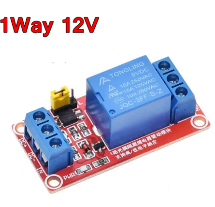
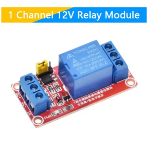
The 1 Channel 12V Relay Module with Optocoupler is a fundamental, yet sophisticated, building block for projects requiring safe, reliable, and isolated control of a single high-power electrical device from a 12V logic system. This compact module serves as a protected interface, allowing a 12V control signal from a PLC, industrial controller, automotive ECU, or timer to safely switch AC or DC loads that operate at much higher voltages and currents. The module’s defining feature is its integrated optocoupler, which creates a complete 2500V electrical isolation barrier between the sensitive 12V control side and the potentially noisy or hazardous load side. This isolation prevents damaging voltage spikes, ground loop currents, and electrical interference generated by motors, solenoids, or AC switching from reaching and damaging your valuable control equipment.
Designed for ultimate flexibility, the module includes a simple jumper to select between high-level or low-level trigger logic, making it compatible with virtually any 12V digital output type. Clear dual-LED indicators provide immediate visual feedback on both the input command status and the relay’s physical switching state. With its high-current relay, secure screw terminals, and straightforward three-pin control interface, this single-channel module is the ideal, reliable solution for adding a single protected switch to 12V-based automation, vehicle systems, industrial controls, or as a modular component in custom panel builds.
Key Features
-
Critical Optical Isolation: Integrated optocoupler provides 2500Vrms of isolation, creating a safe electrical barrier that protects your 12V controller from damaging high-voltage transients and electrical noise from the load side.
-
Selectable Trigger Logic: A simple jumper allows configuration for either High-Level (active on +12V) or Low-Level (active on 0V/GND) trigger operation, ensuring compatibility with any 12V sourcing (PNP) or sinking (NPN) control logic.
-
High-Capacity Relay: Features a durable electromagnetic relay with SPDT (Single Pole Double Throw) contacts, capable of switching loads up to 10A at 250VAC or 30VDC.
-
Dual Status Indication: Two independent LEDs provide clear visual feedback: one lights when the opto-isolator receives a valid input signal, and the other lights when the relay coil is energized and the contacts have physically switched.
-
Integrated Flyback Diode: Includes a protection diode across the relay coil to suppress voltage spikes generated when the coil is de-energized, safeguarding the driving circuitry and ensuring long-term reliability.
-
12V TTL Logic Compatible: Designed for direct and easy interfacing with 12V control systems like PLCs, automotive outputs, or industrial timers, requiring only minimal current (5-10mA) to activate the opto-isolator.
-
Secure & Professional Connections: High-current load connections use reliable screw terminals (COM, NO, NC), while control is via a standard 3-pin header (VCC, GND, IN) for a clean and safe setup.
-
Compact & Versatile Design: A small, self-contained module that is easy to mount and integrate into a wide variety of 12V-based projects, from simple prototypes to final industrial products.
Main Parameters
-
Channels: 1
-
Control Logic Level: 12V DC
-
Trigger Mode: High or Low Level (Jumper Selectable)
-
Isolation Rating: 2500V RMS (Optocoupler)
-
Relay Contact Rating: 10A @ 250VAC / 10A @ 30VDC
-
Relay Type: Electromagnetic, SPDT (Single Pole Double Throw)
-
Input Current: ~5-10mA (to activate optocoupler)
-
Dimensions: Approx. 50mm x 40mm x 20mm
Typical Applications / Usage
-
Industrial Control Interface: Safely connect a single 12V PLC output or sensor to control an actuator, solenoid valve, indicator lamp, or small motor starter in a noisy industrial environment.
-
Automotive/Vehicle Accessory Control: Add a protected, high-current switch for a single accessory (e.g., light bar, air compressor, winch) controlled by a 12V switch, timer, or vehicle computer.
-
Basic Appliance or Lighting Control: Use a 12V timer or sensor to automatically control a single AC appliance (lamp, fan, pump) with complete isolation for safety and noise immunity.
-
Safety Interlock System: Implement a simple, isolated safety circuit where the status of one machine (via a 12V signal) must reliably enable or disable another device.
-
Prototyping & Modular Design: Use as a discrete, reliable switching module that can be easily replicated and integrated into larger custom 12V control panels or system prototypes.
-
Educational Demonstrations: An excellent tool for teaching the principles of relays, optical isolation, and 12V control system design.
Connection & Configuration Guide:
-
Trigger Configuration: Place the jumper cap over the two pins labeled “H” for High-Level trigger (relay activates on a +12V signal) or “L” for Low-Level trigger (relay activates on a 0V signal).
-
Power & Control Wiring: Connect the module’s VCC and GND to a stable 12V DC power source. Connect the signal pin (IN) to the digital output of your 12V controller (PLC, microcontroller, switch).
-
Load Wiring: Connect the power source (e.g., 240V AC line or a 24V DC supply) for your device to the relay’s Common (COM) terminal. Connect the device to be controlled to the Normally Open (NO) terminal to power it when the relay activates, or to the Normally Closed (NC) terminal for the opposite logic.
-
Safety Notice: Always disconnect all high-voltage/high-current power before making or changing any load-side connections. Install the module in a properly rated insulated enclosure for safety and adhere to all local electrical codes.
Q: Why is the optocoupler important in a 12V relay module?
The optocoupler provides essential electrical safety and noise immunity. It prevents any high-voltage spikes, electrical noise, or ground potential differences from the load circuit (e.g., a motor or appliance) from traveling back to and damaging your sensitive 12V controller, which could cause malfunctions or permanent failure.
Q: When should I use High-Level trigger vs. Low-Level trigger?
The choice depends on your controller’s output type.
-
High-Level (H): Use this when your controller provides +12V on its output to activate the switch. This is typical for “sourcing” or PNP outputs.
-
Low-Level (L): Use this when your controller connects the output to ground (0V) to activate the switch. This is typical for “sinking” or NPN outputs. A broken wire in a Low-Level setup often defaults the input to HIGH (via pull-up resistors), turning the relay OFF, which can be a safer “fail-off” design.
Q: Can I use this with a 5V or 24V microcontroller?
Not directly. This module is designed specifically for 12V control logic. A 5V signal will likely be insufficient to activate the optocoupler reliably. A 24V signal will damage it. You must use a module matched to your control voltage or employ appropriate signal conditioning (e.g., a level shifter or voltage divider).
Q: What does the "JD-VCC" pin or jumper do?
On some models, this pin allows you to power the relay coil from a separate 12V power supply than the one powering the optocoupler. This is good practice, as it prevents the relay coil’s inrush current (70-100mA) from causing a voltage drop on the sensitive control logic line. If present, connect your main 12V power to JD-VCC and GND.
Q: What is the difference between the two LEDs?
-
OPTO LED (often green or smaller): Lights up when the optocoupler receives a valid trigger signal from your controller. It indicates the input command has been received.
-
RELAY LED (often red or larger): Lights up when the relay coil is energized and the physical switch contacts have closed. It confirms the output has actually switched and power is available at the load terminals.
Q: Can I use this to switch a DC load, like a 24V DC motor?
Yes, provided you stay within ratings. The relay contacts are rated for both AC and DC. You can switch a 24V DC motor by connecting your 24V DC supply to COM and the motor to NO. Do not exceed the 10A, 30VDC rating.
Q: The relay clicks but my device doesn't turn on. What should I check?
The click confirms the coil is working. The issue is on the load side. 1) Check that your device is connected between COM and NO. 2) Verify the device works by connecting it directly to its power source. 3) Ensure the screw terminals are tightened securely on bare wire ends. 4) Confirm that power is actually present at the COM terminal.
Q: Is this a suitable product for small business or OEM use?
Absolutely. Its professional features—12V compatibility, optical isolation, robust relay, flexible triggering, and secure terminals—make it an excellent, reliable component for low-volume product integration, vehicle upfitting, custom control boxes, and as a spare part for industrial machinery. We offer bulk pricing for business, OEM, and reseller customers. Please contact our sales team for volume quotes.