Product Description
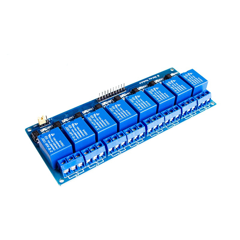
The 5V/12V 8-Channel Opto-Isolated Relay Module is a professional, high-density interface board engineered to serve as a universal, protected output stage for a wide range of microcontroller platforms, including AVR (Arduino), 8051, PIC, and ARM. This module is specifically designed to bridge the gap between low-power 5V or 12V logic signals and the high-power real-world devices they need to control, providing eight completely independent and isolated switching channels. Its standout feature is the dual-voltage compatibility, allowing it to be configured for either 5V or 12V logic levels, making it an exceptionally versatile tool for developers, students, and engineers working across different hardware standards.
Each of the eight channels incorporates advanced optocoupler isolation, creating a 2500V electrical barrier that safeguards your sensitive microcontroller from electrical noise, voltage spikes, and ground loops originating from inductive loads like motors, solenoids, or AC mains. The board features a clear pinout and integrated status LEDs, offering immediate visual feedback for each channel. With its high-current relay outputs, configurable logic levels, and robust screw terminals, this module is the ultimate solution for building sophisticated, reliable, and safe multi-channel control systems for home automation, industrial prototypes, and complex educational projects.
Key Features
-
Dual-Voltage Compatibility: Jumper-selectable 5V or 12V logic level input, making it universally compatible with popular 5V (Arduino/AVR) and 12V (PLC/Industrial) microcontroller families without modification.
-
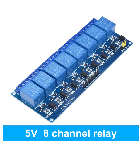
High-Density 8-Channel Design: Control up to eight completely independent AC or DC loads from a single, compact module, maximizing control capability for complex systems.
-
Full Optical Isolation per Channel: Each channel is protected by an independent optocoupler, providing 2500Vrms of isolation to protect your microcontroller from load-side transients and electrical noise.
-
Universal Microcontroller Compatibility: Designed with a standard pin header interface that directly connects to the I/O ports of AVR (Arduino), 8051, PIC, and other common microcontrollers.
-
High-Current Relay Outputs: Eight industrial-grade electromagnetic relays with SPDT contacts, each capable of switching loads up to 10A, suitable for a vast range of appliances and equipment.
-
Comprehensive Status Indicators: Dual LEDs per channel provide clear visual diagnostics: one for opto-isolator input status and one for physical relay activation.
-
Secure & Robust Connections: All high-power load connections and DC inputs utilize reliable screw terminals for safe, vibration-resistant wiring in demanding applications.
-
Integrated Protection Circuits: Each channel includes flyback diodes and other protective components to ensure long-term reliability and protect both the module and the connected microcontroller.
Main Parameters
-
Channels: 8 Independent Relays
-
Logic Voltage: 5V or 12V DC (Jumper Selectable)
-
Control Interface: Standard 0.1″ pin header for direct MCU connection
-
Isolation Rating: 2500V RMS (Optocoupler, per channel)
-
Relay Contact Rating: 10A @ 250VAC / 10A @ 30VDC
-
Relay Type: Electromagnetic, SPDT (Single Pole Double Throw)
-
Input Current (per channel): ~5-10mA (to activate optocoupler)
-
Dimensions: Approx. 145mm x 100mm x 25mm
Typical Applications / Usage
-
Multi-Platform Development & Prototyping: A single, universal output module for engineers and students developing projects across different microcontroller families (AVR, 8051, PIC), eliminating the need for multiple relay boards.
-
Complex Home Automation Controller: Build a central, silent hub for a smart home system using an Arduino (5V) or a more industrial 12V controller to manage up to eight different appliances or lighting zones.
-
Industrial Control Prototyping: Interface a 12V PLC or a 5V industrial microcontroller with multiple actuators, solenoids, and indicators in a machine prototype or test fixture.
-
Educational Laboratory Setup: An ideal teaching tool for university labs, allowing students to learn interfacing and control principles with various microcontroller platforms on a single, reliable piece of hardware.
-
Exhibit & Display Control: Create dynamic, multi-device control systems for museum exhibits, trade show booths, or interactive art installations, adaptable to the controller on hand.
-
Data Acquisition & Test Systems: Use as the robust output stage for custom data acquisition setups or environmental test chambers, controlling heaters, lamps, and stirrers.
Connection & Configuration Guide:
-
Voltage Configuration: Set the logic-level jumper to select either 5V or 12V, matching the operating voltage of your microcontroller’s I/O pins.
-
Control & Power Wiring: Connect the module’s VCC and GND to a power supply matching your selected logic voltage (5V or 12V). Connect the eight signal pins (IN1-IN8) directly to the I/O port pins of your microcontroller (e.g., PORTB on an AVR, P1 on an 8051).
-
Load Wiring: For each channel, connect the power source for your load (AC mains or DC) to the relay’s Common (COM) terminal. Connect the device to be controlled to the Normally Open (NO) terminal to be powered when the relay activates.
-
Critical Safety: Always disconnect all high-voltage power before making load-side connections. This module must be installed in a properly rated enclosure. Follow all local electrical codes, especially when switching AC mains voltage.
Q: What does "for AVR/51/PIC Microcontrollers" mean?
It means the module’s control interface is designed as a simple, standard pin header that can be directly connected to the digital I/O ports of these popular microcontroller families. The pin spacing and signal levels are compatible, so you can connect it directly with jumper wires or a ribbon cable without needing additional driver circuits.
Q: How do I choose between 5V and 12V mode?
You must select the mode that matches the logic HIGH voltage of your microcontroller’s output pins.
-
If your microcontroller (like Arduino, most AVRs) uses 5V logic, set the jumper to 5V.
-
If your controller (like some PLCs or industrial boards) uses 12V logic, set the jumper to 12V.
Using the wrong setting can result in the module not triggering (if 5V on a 12V setting) or potential damage (if 12V on a 5V setting).
Q: I'm using a 3.3V microcontroller (like some ARM or ESP). Can I use the 5V setting?
It may not be reliable. A 3.3V signal is below the standard 5V TTL “HIGH” threshold. The optocoupler might not activate consistently. For reliable operation with 3.3V logic, it is recommended to use a simple logic level converter (3.3V to 5V) on the signal lines, or use a transistor to drive the module’s input.
Q: What is the power consumption of the module?
Power consumption has two parts:
-
Control Side (opto-couplers): Very low, ~5-10mA per active channel from your selected logic voltage (5V/12V).
-
Relay Coils: This is the main draw. Each relay coil requires ~70-80mA when activated. With all 8 relays on, the module can draw ~600mA. You must provide a separate, adequately rated 5V or 12V supply (based on your jumper setting) capable of this current to the module’s power terminals.
Q: Does the optical isolation protect my microcontroller?
Yes, absolutely. The primary purpose of the optocouplers is to protect your microcontroller. They prevent any high-voltage transients, electrical noise, or ground potential differences on the load side (where you connect motors, lights, etc.) from traveling back into the sensitive digital I/O pins of your AVR, PIC, or 8051 chip.
Q: Can I use this to control 3-phase equipment or very high-power devices?
No, not directly for high-power loads. The relays are single-pole and rated for 10A. For 3-phase motors or high-wattage heaters, you should use one channel of this module to control the coil of an appropriately rated contactor or motor starter, which is designed to handle the high-power load safely.
Q: The opto LED lights but the relay doesn't click. Why?
This indicates the control signal is being received, but the relay coil is not getting power. The most common reason is that the relay coil power is separate from the logic power. Ensure you have connected a sufficiently powerful 5V or 12V supply (matching your jumper setting) to the module’s main VCC and GND terminals to power the coils. The opto-coupler and relay coil often use the same supply but on different internal circuits.
Q: Is this module suitable for final product integration or just for prototyping?
While it is an excellent prototyping and development tool, its professional features (isolation, high-density, dual-voltage, robust construction) also make it suitable for integration into low-to-medium volume commercial products, educational kits, and specialized equipment where a versatile, reliable output stage is required. For high-volume OEM, contact us for custom solutions.