Description
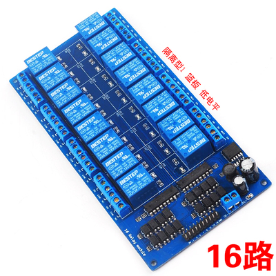
The 16-Channel Relay Module 12V is a professional-grade, high-density control board designed for systems that require reliable switching of up to sixteen independent high-power loads using 12V logic control. Unlike standard 5V relay modules, this board operates natively with 12V control signals — making it an ideal match for industrial PLCs, automotive electronics, 12V battery-powered systems, and many commercial control panels.
Each of the 16 channels features optocoupler isolation, providing complete electrical separation between your 12V controller and the high-voltage load side. This protects your control system from voltage spikes, back EMF, and ground loop noise. The onboard LM2596 DC-DC step-down power supply allows you to power the entire relay bank from a wide input voltage range (typically 8V–35V DC) while delivering a stable 12V to the relay coils and optocoupler circuits — eliminating the need for a separate 12V power supply, even when all 16 relays are activated simultaneously.
Visible LED indicators per channel provide clear status feedback, and the robust screw terminals ensure secure high-voltage wiring. Whether you are upgrading an industrial machine, building a 12V automation system, or deploying a large-scale lighting controller, this 16-channel 12V relay module delivers reliability, safety, and scalability.
Features
-
16 independent relays with optocoupler isolation per channel
-
Native 12V logic control — compatible with PLCs and 12V systems
-
Onboard LM2596 switching power supply (8V–35V DC input → stable 12V output)
-
Eliminates external 12V power supply — runs from a single higher-voltage source
-
Active HIGH trigger (12V TTL logic compatible)
-
LED indicators for each relay channel
-
Screw terminals for all high-voltage connections
-
Standard 2.54mm pin header for control signals
-
Optocoupler protection for controller I/O pins
-
Suitable for AC (250V/10A) and DC (30V/10A) loads
Technical Parameters
Usage Guide
1. Powering the Module
The onboard LM2596 regulator allows flexible power input and outputs a stable 12V:
Connect your DC power supply to the VIN and GND terminals. The LM2596 will generate stable 12V internally for relay coils.
2. Connecting to a 12V Controller (e.g., PLC, 12V Arduino, or 12V I/O Module)
For 24V PLCs with 24V outputs, use a 24V-to-12V level shifter or resistor divider (the module expects 12V logic, not 24V).
3. Connecting to a 5V Microcontroller (Arduino, ESP32)
If you only have a 5V controller but want to use this 12V relay module:
-
Use a logic level shifter (5V → 12V) or a transistor buffer circuit
-
Alternatively, power the module via VIN (12V–24V) and use an external 12V supply for the logic signals
-
Do NOT connect 5V logic directly — it will not reliably trigger the 12V optocouplers
4. AC/DC Load Wiring
Each relay has three screw terminals:
-
COM (Common) – Connect to live/positive supply
-
NO (Normally Open) – Connect to load’s live/positive input
-
NC (Normally Closed) – Unused or alternate circuit
Example (AC motor control):
AC Live ──→ COM
AC Neutral ──→ Motor Neutral
Motor Live ──→ NO
5. Sample PLC Ladder Logic (12V Output)
For a typical 12V PLC output module (e.g., Siemens LOGO!, Click PLC, or AutomationDirect):
// Rung 1: Turn on Relay 1 when Input X1 is ON
---| X1 |-------------------( Y1 )---
// Y1 connects to IN1 of the relay module
6. Sample Arduino Code (with 5V→12V Level Shifter)
int relayPins[16] = {2,3,4,5,6,7,8,9,10,11,12,13,14,15,16,17};
void setup() {
for (int i = 0; i < 16; i++) {
pinMode(relayPins[i], OUTPUT);
digitalWrite(relayPins[i], LOW);
}
}
void loop() {
digitalWrite(relayPins[0], HIGH);
delay(2000);
digitalWrite(relayPins[0], LOW);
delay(2000);
}
7. Important Notes
-
Always connect module GND to your controller GND for signal reference.
-
The module expects 12V logic signals (10V–14V range). Lower voltages may not trigger reliably.
-
For 16 relays all active simultaneously, ensure your input power supply can deliver sufficient current (see FAQ).
-
The optocoupler isolation protects your controller, but the load side still requires proper fusing and safety enclosures.
Q: Why choose the 12V version instead of the 5V version?
The 12V version is designed for native compatibility with:
-
Industrial PLCs with 12V outputs
-
Automotive and marine electronics (12V battery systems)
-
12V sensor and control networks
-
Commercial building automation (many HVAC controllers use 12V logic)
If your control system already uses 12V, this module eliminates the need for level shifters or voltage conversion.
Q: Can I use this module with a 24V PLC?
Not directly. The module expects 12V logic signals. Connecting 24V directly to IN1–IN16 will damage the optocoupler input circuits. Solutions:
Q: Can I use this module with a 5V microcontroller (Arduino, ESP32)?
Only with a 5V → 12V logic level shifter. The 12V optocoupler requires approximately 8V–14V to trigger reliably. A 5V signal will not work. We offer a 5V version of this 16-channel module — we recommend that for Arduino users.
Q: What is the advantage of having an LM2596 power supply on board?
The LM2596 allows you to power the module from a single higher-voltage supply (e.g., 24V industrial rail) while generating clean 12V for the relay coils internally. Without it, you would need a separate 12V power supply capable of delivering ~1.2A for all relays. The LM2596 simplifies wiring and reduces component count.
Q: What input voltage range does the LM2596 accept?
The LM2596 on this module is configured for 8V – 35V DC input. For stable 12V output, the input must be at least 2V higher than the output (so minimum 14V is recommended for full performance, but 8V–12V input will still work with reduced output regulation).
Q: How much current does the module draw from the input supply?
-
Idle (all relays OFF) : ~30–50mA
-
One relay ON : ~70–80mA (at 12V coil)
-
All 16 relays ON : ~1.2A – 1.3A at 12V coil equivalent
At 24V input, the LM2596 draws approximately 650mA–700mA to produce 1.2A at 12V (considering efficiency). Recommend an input supply rated at least 24V / 1A for full 16-channel operation.
Q: What is the purpose of optocoupler isolation?
Optocouplers provide complete electrical separation between your 12V controller and the relay coils / AC loads. This protects your expensive PLC or control system from:
-
Back EMF from inductive loads (motors, solenoids, contactors)
-
Voltage spikes from AC mains switching
-
Ground loops in industrial environments
Q: Is this module suitable for controlling 16 independent AC appliances?
Absolutely. Each relay is fully independent. You can mix AC and DC loads, different voltages, and different currents across channels, as long as each stays within 10A / 250V AC or 30V DC.
Q: Can I use this module in a vehicle (12V automotive system)?
Yes, with caution. The module accepts 8V–35V input, so a standard 12V automotive system (typically 11V–14.5V) is within range. However, automotive environments have voltage spikes (load dump, alternator noise). We recommend adding a TVS diode (e.g., 1.5KE24A) across VIN/GND for protection. Also ensure the enclosure is vibration-resistant.
Q: Can I use this module for business / industrial automation?
Yes, this is designed for professional use, including:
-
PLC output expansion (12V PLCs like Siemens LOGO! 12V models)
-
Industrial machinery retrofitting
-
Building management systems (HVAC, lighting, access control)
-
Marine and RV automation (12V house batteries)
-
Automated test equipment (ATE)
-
Agricultural controls (irrigation, greenhouse fans)
The combination of 12V logic, optocoupler isolation, onboard power regulation, and 16 channels makes it a drop-in solution for many industrial applications.
Q: How do I know if the optocoupler is working correctly?
When the 12V control signal is applied, the relay should click and the LED light. The optocoupler’s function is transparent — if the relay responds correctly and your controller remains protected (no back EMF damage), the optocoupler is functioning.
Q: Can I mount this module on a DIN rail?
Yes. The board dimensions (approx. 200mm × 110mm) are compatible with standard DIN rail mounting brackets (available separately). Contact us for DIN rail clip options and panel mounting accessories.
Q: What is the lifespan of the relays on this module?
Mechanical relays are rated for approximately 100,000 – 1,000,000 switching cycles depending on load current and type. For high-frequency switching (>10 times per minute), consider our Solid State Relay (SSR) modules instead.
Q: What happens if I supply more than 35V to VIN?
The LM2596 has an absolute maximum input rating of 40V. Exceeding 35V continuously may destroy the regulator and potentially send overvoltage to the relay coils. Always stay within the specified range.
Q: Does the LM2596 require a heatsink?
The LM2596 is an efficient switching regulator (typically 80–90%). For 24V input and all 16 relays continuously active, the regulator may become warm (40–50°C) but typically does not require a heatsink. Ensure adequate airflow around the module. For 35V input and continuous full load, consider adding a small heatsink to the LM2596.