Description
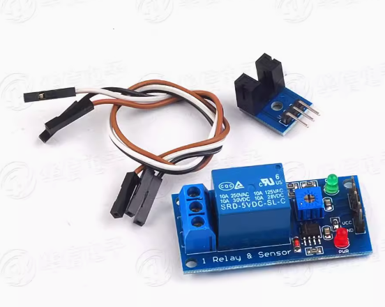
The 5V Speed Measuring Relay Module is a compact, intelligent speed monitoring and control device designed for low-voltage automation systems. Operating on a standard 5V DC supply—making it compatible with USB power, Arduino, Raspberry Pi, and other microcontroller platforms—this module detects rotational speed or pulse frequency from sensors and triggers a built-in relay when user-defined speed thresholds are crossed.
The module accepts input signals from a variety of sensors, including Hall effect sensors, proximity switches (NPN/PNP), optical interrupters, and magnetic pickups. When the measured speed (in Hz, RPM, or user-scaled units) falls below or exceeds the preset value, the relay activates or deactivates connected equipment such as cooling fans, alarms, conveyor motors, or warning lights.
With an intuitive interface featuring a digital display and push-button controls, users can set trigger speeds, select overspeed or underspeed monitoring modes, adjust start-up delay times, and configure hysteresis to prevent relay chatter. Housed in a compact, panel-mountable enclosure, this module is ideal for DIY tachometer projects, small motor protection, conveyor belt slip detection, fan speed monitoring, and educational labs—all without requiring complex PLC programming.
Key Features
-
5V DC Operation – Compatible with USB power banks, Arduino, Raspberry Pi, and standard 5V power supplies.
-
Overspeed & Underspeed Monitoring – Selectable mode to trigger relay when speed exceeds OR falls below setpoint.
-
Wide Frequency Measurement Range – Detects signals from approximately 0.5 Hz up to several kHz, suitable for most small motors and rotating machinery.
-
Built-in SPDT Relay – Controls external devices up to 10A / 250V AC or 10A / 30V DC.
-
Adjustable Start-Up Delay – Prevents false alarms during motor start-up by ignoring speed readings for a configurable period (e.g., 1–30 seconds).
-
Adjustable Hysteresis – User-set switching differential prevents rapid relay cycling near threshold.
-
Real-Time Speed Display – Digital screen shows current frequency (Hz) or scaled RPM value.
-
Non-Volatile Memory – All settings are saved permanently, even after power loss.
Technical Parameters
Usage Guide
Wiring Instructions
Step 1 – Power Connection
Step 2 – Sensor Connection
-
Hall Effect Sensor / NPN Output : Connect sensor VCC to 5V, GND to GND, and signal wire to the SIG input terminal.
-
PNP Output Sensor : Check module compatibility (some modules require a voltage divider or level shifter; refer to markings).
-
Mechanical Switch / Opto-interrupter : Connect across SIG and GND.
Step 3 – Load (Device) Connection
-
COM (Common): Connect to your power source (AC or DC live/positive line).
-
NO (Normally Open): Relay closes when speed threshold is reached. Connect to device input.
-
NC (Normally Closed): Relay opens when speed threshold is reached. Use for reverse logic.
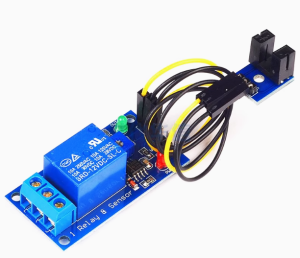
Step 4 – Sensor Placement
-
Mount the speed sensor near the rotating target (e.g., magnet on a motor shaft, reflective tape, or encoder disc). Ensure proper gap and alignment per sensor specifications.
Configuration Steps
Programming Steps:
-
Power on the module. Display shows real-time frequency (Hz) from the sensor.
-
Press SET once – the trigger value blinks. Use UP/DOWN to set desired speed threshold.
-
Press SET again – mode selection. Choose:
-
Press SET again – start-up delay (usually shown as “dt”). Set 1–30 seconds as needed.
-
Press SET again – hysteresis value. Set 1%–30% to prevent rapid switching.
-
Wait 5 seconds – display returns to normal; settings saved.
Example (Cooling Fan Overspeed Protection):
-
Set trigger = 3000 Hz, mode = H (overspeed), start delay = 5 sec, hysteresis = 5%.
→ Relay activates if fan speed exceeds 3000 Hz for more than 5 seconds; resets when speed drops below 2850 Hz.
Q: What type of sensors can I use with this module?
The module accepts NPN open-collector outputs (most common), Hall effect sensors, proximity switches (3-wire NPN), optical interrupters, and TTL pulse signals (0–5V). For PNP sensors, a level shifter or voltage divider may be required.
Q: Can I use this with an Arduino or Raspberry Pi?
Yes. The 5V operating voltage is ideal for Arduino (direct connection) and Raspberry Pi (use a separate 5V supply; do not draw relay coil current from the Pi’s 5V pin). You can also feed a pulse signal directly from an Arduino digital pin for testing.
Q: How do I convert Hz to RPM?
RPM = (Frequency in Hz × 60) ÷ (number of pulses per revolution). For example, with one magnet on a shaft (1 pulse/revolution), 10 Hz = 600 RPM. The module may have a scaling function; check the manual.
Q: My relay clicks on and off rapidly. What should I do?
Increase the hysteresis value. For example, change from 5% to 15%. This creates a larger “deadband” between ON and OFF points, preventing chatter when speed fluctuates near the threshold.
Q: Why does my module trigger immediately at power-up?
This is normal if the start-up delay is set too low. Increase the start-up delay (dt) to 5–10 seconds. During this time, the relay remains in its normal (non-alarm) state regardless of speed reading.
Q: Can I use this to monitor both overspeed and underspeed simultaneously?
The module monitors one threshold at a time (either overspeed OR underspeed). For dual-threshold applications (e.g., both low-speed and high-speed alarms), two modules or a more advanced controller would be required.
Q: What is the maximum frequency this module can measure?
The module reliably measures up to 5 kHz (5000 pulses per second) . For a single magnet per revolution, this equals 300,000 RPM. Higher frequencies may cause missed pulses.
Q: Can I power this module from the same 5V supply as my sensor?
Yes, provided the power supply can deliver sufficient current (module ≤80 mA + sensor current). A standard USB power supply (500mA–2A) is usually sufficient.
Q: Does this module work for home and business applications?
Home users: DIY tachometers, aquarium pump monitors, 3D printer filament runout detection, fan speed alarms.
Business users: Conveyor belt slip detection, small motor over-speed protection, packaging line monitoring, educational lab equipment, HVAC fan verification.
Q: What is the difference between NO and NC relay outputs?
-
NO (Normally Open) : Relay is open (off) when speed is normal; closes (turns on) when alarm condition occurs.
-
NC (Normally Closed) : Relay is closed (on) when speed is normal; opens (turns off) when alarm condition occurs.