Description
The 2-Channel 5V Opto-Isolated Relay Module is a professional-grade, dual-channel switching solution designed for microcontroller-based automation, PLC systems, and industrial control applications. Operating on a standard 5V DC supply—compatible with Arduino, Raspberry Pi, ESP32, STM32, 8051, AVR, PIC, DSP, ARM, and TTL logic devices—this module enables safe and reliable control of high-power AC and DC loads using low-voltage logic signals .
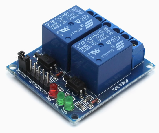
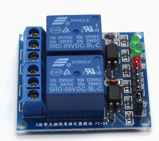
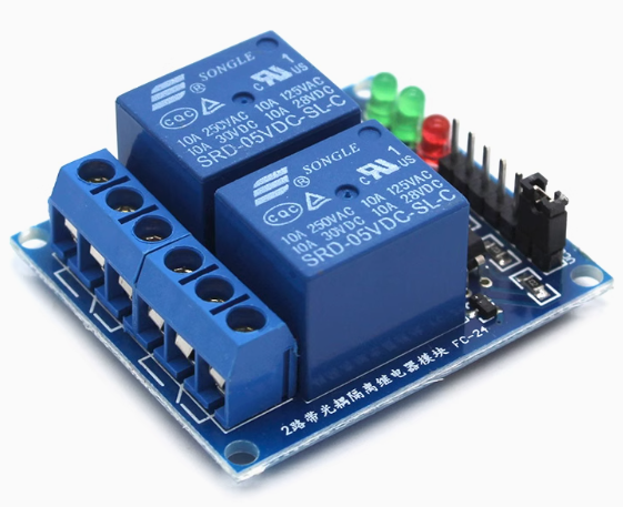
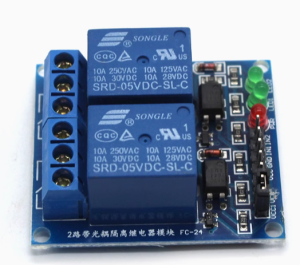
Each of the two independent channels features a Single-Pole Double-Throw (SPDT) relay rated for 10A at 250V AC or 30V DC, making it suitable for controlling lights, motors, pumps, solenoids, fans, and household appliances . The module incorporates optocoupler isolation between the control side and the load side, providing complete galvanic isolation that protects your sensitive microcontroller from voltage spikes, back EMF, and electrical noise generated by inductive loads .
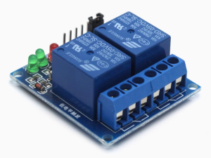
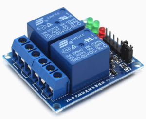
The module includes a jumper-selectable high/low level trigger function, allowing you to configure each channel independently for active-high or active-low operation without modifying your code or hardware . Dual LED indicators—a red power LED and two green status LEDs—provide clear visual feedback of relay states. An additional VCC-JD-VCC jumper allows optional separation of the relay power supply from the logic power supply, enabling you to power the relays from an external source for heavy-load applications .
The PCB features four 3.1mm mounting holes for secure installation and is compatible with DIN rail mounting adapters (sold separately). The screw terminal blocks provide reliable, vibration-resistant connections for load wiring, while the 4-pin male header (2.54mm pitch) accepts standard Dupont jumper wires for easy integration with development boards .
Whether you are building a smart home automation system, controlling industrial machinery, managing greenhouse irrigation, or prototyping an Arduino-based project, this 2-channel relay module delivers robust, isolated, and flexible switching performance in a compact, easy-to-use package.
Key Features
-
Dual Independent Channels – Two SPDT relays allow simultaneous control of two separate loads with individual trigger inputs .
-
Opto-Isolated Inputs – Complete galvanic isolation between control logic and load circuits protects microcontrollers from voltage spikes and electrical noise .
-
Selectable Trigger Mode – Jumper-configurable per channel for High-Level Trigger (active HIGH) or Low-Level Trigger (active LOW) operation .
-
10A High-Current Relays – Each relay rated for 10A at 250V AC or 30V DC, suitable for controlling lights, motors, pumps, and household appliances .
-
SPDT Contact Configuration – Each relay provides Normally Open (NO), Normally Closed (NC), and Common (COM) terminals for flexible wiring .
-
Separate Relay Power Option – VCC-JD-VCC jumper allows the relay coils to be powered from an external source for heavy-load applications .
-
LED Status Indicators – Green power LED and two red relay status LEDs provide clear visual confirmation of operation .
-
Wide Logic Compatibility – Works with 3.3V and 5V logic signals from Arduino, Raspberry Pi, ESP32, STM32, and other microcontrollers .
-
Screw Terminal Connections – Heavy-duty screw terminal blocks for reliable load wiring and easy installation .
-
Compact Form Factor – 50mm x 41mm x 18.5mm dimensions with 3.1mm mounting holes for secure installation; compatible with DIN rail adapters .
Technical Parameters
Usage Guide
How It Works
The module uses an optocoupler to isolate the low-voltage control side (connected to your microcontroller) from the high-voltage load side. When the trigger input (IN1 or IN2) receives the appropriate signal (HIGH or LOW depending on jumper configuration), the optocoupler activates, which energizes the relay coil. The energized relay switches the common (COM) terminal connection from the normally closed (NC) contact to the normally open (NO) contact, completing the circuit to your load .
The VCC-JD-VCC jumper (typically located near the power input header) connects the logic power supply to the relay coil power supply. When driving heavy loads or multiple relays simultaneously, you can remove this jumper and supply separate power to the JD-VCC pin to avoid overloading your microcontroller’s 5V regulator .
Wiring Instructions
Step 1 – Control Side Connection (to Microcontroller)
Connect the 4-pin male header (2.54mm pitch) as follows:
Step 2 – Load Side Connection (to High-Power Device)
Each relay channel has a 3-pin screw terminal block:
Wiring Example 1 – Controlling an AC Light Bulb (NO configuration):
-
Connect AC Live wire → COM terminal
-
Connect AC Neutral wire → Light bulb neutral
-
Connect Light bulb live → NO terminal
-
When relay activates, the circuit closes and the light turns ON
Wiring Example 2 – Controlling a DC Motor (NO configuration):
-
Connect DC power supply positive → COM terminal
-
Connect Motor positive → NO terminal
-
Connect Motor negative → DC power supply negative directly
⚠️ Safety Warning: High voltage (110V/220V AC) is dangerous. Ensure all connections are properly insulated. Always disconnect power before wiring. Use appropriately gauged wire for your load current. Mount the module in an enclosure for permanent installations.
Trigger Mode Configuration (High/Low Level Jumper)
The module features jumper-selectable trigger modes, typically labeled S1 and S2 (one for each channel) or a single H/L jumper with individual channel selection .
Common Configurations:
-
Arduino (5V logic) : Set jumper to HIGH position – relay activates when digitalWrite(pin, HIGH)
-
Raspberry Pi (3.3V logic) : Set jumper to LOW position – relay activates when GPIO.output(pin, GPIO.LOW)
-
Push-button control : Set to LOW position – connect button between IN pin and GND
To change trigger mode:
-
Locate the jumper on the PCB (usually a small black plastic cap covering two or three header pins)
-
Gently remove the jumper cap
-
Reposition it over the desired pins (refer to silkscreen labels: LOW/GND or HIGH/VCC)
-
Each channel may have its own jumper – configure independently
VCC-JD-VCC Jumper (Separate Relay Power Option)
By default, a jumper connects VCC to JD-VCC, powering the relay coils from the same 5V supply as the logic circuit.
When to remove the jumper:
-
Controlling multiple relays simultaneously (high total coil current)
-
Using a low-current 5V supply (e.g., USB from a computer)
-
Driving heavy inductive loads that cause voltage fluctuations
How to use separate power:
-
Remove the VCC-JD-VCC jumper cap
-
Connect external 5V supply to JD-VCC pin (positive) and GND pin (negative)
-
Connect microcontroller 5V to VCC pin (positive) and same GND pin
-
The logic and relay circuits are now independently powered
Arduino Sample Code (Low-Level Trigger Configuration)
const int RELAY1 = 7;
const int RELAY2 = 8;
void setup() {
pinMode(RELAY1, OUTPUT);
pinMode(RELAY2, OUTPUT);
digitalWrite(RELAY1, HIGH);
digitalWrite(RELAY2, HIGH);
}
void loop() {
digitalWrite(RELAY1, LOW);
delay(2000);
digitalWrite(RELAY1, HIGH);
delay(1000);
digitalWrite(RELAY2, LOW);
delay(2000);
digitalWrite(RELAY2, HIGH);
delay(1000);
}
Installation Tips
-
Mounting: Secure the module using the four 3.1mm mounting holes with M3 screws or double-sided tape. For DIN rail mounting, use an optional DIN rail adapter bracket .
-
Ventilation: Allow adequate airflow around the module, especially when switching high currents continuously.
-
Wire Gauge: Use 14-22 AWG wire for load connections depending on current. For 10A loads, minimum 18 AWG copper wire is recommended.
-
Enclosure: For permanent installations, mount the module inside a UL-listed electrical enclosure with appropriate strain relief.
Q: What is the difference between High-Level Trigger and Low-Level Trigger?
The module includes jumpers to select the trigger mode per channel
Q: Can I use this module with a 3.3V microcontroller like Raspberry Pi or ESP32?
Yes. The optocoupler inputs are compatible with 3.3V logic signals. For reliable operation, set the trigger jumper to LOW position (Active LOW) and drive the IN pins LOW to activate the relays . The module still requires 5V power for the relay coils.
Q: What is the purpose of the VCC-JD-VCC jumper?
This jumper connects the logic power supply (VCC) to the relay coil power supply (JD-VCC). By default, both are powered from the same 5V source. Removing the jumper allows you to:
-
Power relays from a separate, higher-current 5V supply
-
Reduce load on your microcontroller’s 5V regulator
-
Provide cleaner power for sensitive logic circuits
Q: What types of loads can I control with this relay?
The 10A/250V AC rating allows control of:
-
AC loads: Lights, fans, pumps, solenoid valves, small motors, heaters, appliances
-
DC loads: LED strips, DC motors (within 30V/10A rating), automotive accessories
For inductive loads (motors, solenoids, transformers), consider adding an external snubber or flyback diode to protect relay contacts from voltage spikes.
Q: Can I use this module for both home and business applications?
Home users: Smart home lighting control, automated garden irrigation, aquarium pump control, garage door automation, DIY security systems, holiday light displays.
Business users: Industrial equipment control, PLC output expansion, conveyor system control, greenhouse environmental control, vending machine automation, laboratory equipment switching, HVAC damper control, signage lighting.
Q: How much current does each input pin draw?
Each trigger input draws approximately 5mA to 20mA when activated . Most microcontrollers can drive this directly. For multiple channels simultaneously, ensure your microcontroller’s total output current does not exceed its rating (typically 200mA for Arduino).
Q: What happens if I connect the power supply in reverse?
The module does not include reverse polarity protection on most models. Connecting VCC to GND and GND to VCC can permanently damage the optocouplers and relays. Always double-check connections before applying power.
Q: Can I use this module to control both AC and DC loads simultaneously?
Yes. Each relay channel is independent. You can connect an AC load (e.g., 120V light) to Channel 1 and a DC load (e.g., 12V motor) to Channel 2. The optocoupler isolation ensures no cross-interference between channels.
Q: Why does my relay click but the load does not turn on?
Possible causes:
-
Incorrect trigger mode: Check jumper settings (HIGH vs LOW) match your code
-
Wiring error: Verify COM and NO/NC connections
-
Load exceeds rating: Check if your load current exceeds 10A
-
Power supply insufficient: Ensure the 5V supply can provide sufficient current for both relays (up to 160mA when both active)
Q: How do I know if the relay is ON or OFF?
The module provides two indicators:
You can also hear an audible “click” when the relay switches.