4 Channel Relay Module with light coupling 5V

SKU: FA2088
Operating Voltage

5V DC (±10%) (4.5V – 5.5V)

Operating Current

≤ 30 mA (all relays idle) / ≤ 240 mA (all relays active, ~60mA per channel)

Trigger Current per Channel

5mA – 20mA (optocoupler input)

Trigger Modes

High-Level (active HIGH) or Low-Level (active LOW) – jumper selectable per channel

Relay Contact Rating

10A / 250V AC or 10A / 30V DC (resistive load per channel)

Output Configuration

SPDT per channel – COM, NO, NC terminals

Isolation Method

Optocoupler (PC817 or equivalent) – full galvanic isolation

Module Dimensions

73 x 50 x 18.5 mm (L x W x H)

Operating Temperature

-40°C to +85°C

Description

The 4 Channel Relay Module with Optocoupler 5V is a professional-grade, quad-channel switching solution designed for microcontroller-based automation, PLC systems, and industrial control applications. Operating on a standard 5V DC supply—compatible with Arduino, Raspberry Pi, ESP32, STM32, 8051, AVR, PIC, ARM, and other TTL logic devices—this module enables safe and reliable control of up to four independent high-power AC or DC loads using low-voltage logic signals .

What sets this module apart is its optocoupler isolation technology . Each of the four channels features an independent optocoupler (typically PC817) that provides complete galvanic isolation between the low-voltage control side (connected to your microcontroller) and the high-voltage load side. This protects your sensitive microcontroller from voltage spikes, back EMF, and electrical noise generated by inductive loads such as motors, solenoids, and pumps .

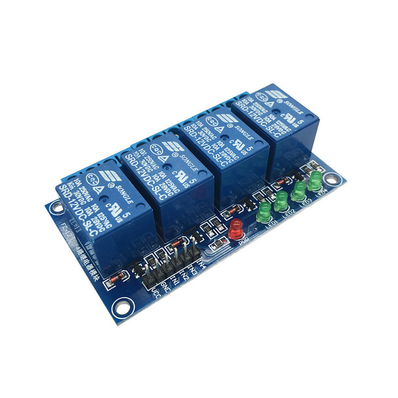
Each relay is a Single-Pole Double-Throw (SPDT) type rated for 10A at 250V AC or 10A at 30V DC, making it suitable for controlling lights, fans, motors, pumps, solenoids, heaters, and household appliances . The module features jumper-selectable high/low level trigger options per channel, allowing you to configure each relay independently for active-high or active-low operation without modifying your code .

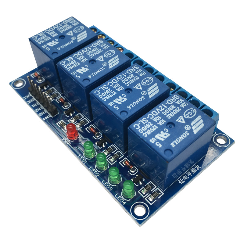
LED indicators provide clear visual feedback: a green power LED shows module status, and four individual red LEDs illuminate when each corresponding relay is energized . The PCB includes a VCC-JD-VCC jumper that allows optional separation of the relay power supply from the logic power supply, enabling you to power the relays from an external source for heavy-load applications . An isolation slot on the PCB physically separates the control area from the load area, enhancing safety and meeting international standards .

The module features heavy-duty screw terminal blocks for reliable load connections and a 4-pin male header (2.54mm pitch) for easy connection to your microcontroller. Four mounting holes (3.1mm diameter) at each corner allow for secure installation in enclosures or on DIN rails using optional adapters .

Whether you are building a smart home automation system, controlling industrial machinery, managing greenhouse irrigation, or prototyping an Arduino-based project, this 4-channel optocoupler relay module delivers robust, isolated, and flexible switching performance in a compact, easy-to-use package.

Key Features

  • 4 Independent Channels – Control up to four separate loads simultaneously with individual trigger inputs

  • Optocoupler Isolation per Channel – Complete galvanic isolation (PC817 or equivalent) protects microcontrollers from voltage spikes and electrical noise

  • 10A High-Current Relays – Each relay rated for 10A at 250V AC or 10A at 30V DC, suitable for controlling lights, motors, pumps, and household appliances

  • SPDT Contact Configuration – Each relay provides Normally Open (NO), Normally Closed (NC), and Common (COM) terminals for flexible wiring

  • Selectable Trigger Mode per Channel – Jumper-configurable for High-Level Trigger (active HIGH) or Low-Level Trigger (active LOW) operation

  • Separate Relay Power Option – VCC-JD-VCC jumper allows relay coils to be powered from an external source to avoid overloading your microcontroller

  • Physical Isolation Slot – PCB cutout separates control and load areas, enhancing safety and meeting international standards

  • LED Status Indicators – Green power LED and four individual red relay status LEDs provide clear visual feedback

  • Low Trigger Current – Only 5-20mA trigger current per channel, safe for direct microcontroller connection

  • Compact Form Factor – 73mm x 50mm x 18.5mm dimensions with 3.1mm mounting holes for secure installation

Technical Parameters

Parameter Value
Operating Voltage 5V DC (±10%) (4.5V – 5.5V)
Operating Current ≤ 30 mA (all relays idle) / ≤ 240 mA (all relays active, ~60mA per channel)
Trigger Current per Channel 5mA – 20mA (optocoupler input)
Trigger Modes High-Level (active HIGH) or Low-Level (active LOW) – jumper selectable per channel
Relay Contact Rating 10A / 250V AC or 10A / 30V DC (resistive load per channel)
Output Configuration SPDT per channel – COM, NO, NC terminals
Isolation Method Optocoupler (PC817 or equivalent) – full galvanic isolation
Module Dimensions 73 x 50 x 18.5 mm (L x W x H)
Operating Temperature -40°C to +85°C

Usage Guide

How It Works

The module uses an independent optocoupler for each channel to isolate the low-voltage control side from the high-voltage load side. When the trigger input (IN1, IN2, IN3, or IN4) receives the appropriate signal (HIGH or LOW depending on jumper configuration), the optocoupler activates, which energizes the corresponding relay coil . The energized relay switches the common (COM) terminal connection from the normally closed (NC) contact to the normally open (NO) contact, completing the circuit to your load .

The VCC-JD-VCC jumper (typically located near the power input header) connects the logic power supply to the relay coil power supply. When driving multiple relays simultaneously, you can remove this jumper and supply separate power to the JD-VCC pin to avoid overloading your microcontroller’s 5V regulator .

Important Operating Principle: For most 4-channel optocoupler relay modules, the relay activates when the input signal is LOW (0V) by default . This is because the optocoupler LED is typically wired with its anode to VCC and cathode to the IN pin. When the IN pin is pulled LOW, current flows through the LED, activating the optocoupler and relay .

Wiring Instructions

Step 1 – Control Side Connection (to Microcontroller)

Connect the 4-pin male header (2.54mm pitch) as follows:

Pin Label Connection
1 VCC or DC+ Connect to 5V output of microcontroller or external 5V supply
2 GND or DC- Connect to ground (GND) of microcontroller
3 IN1 Connect to digital output pin (controls Channel 1 relay)
4 IN2 Connect to digital output pin (controls Channel 2 relay)
5 IN3 Connect to digital output pin (controls Channel 3 relay)
6 IN4 Connect to digital output pin (controls Channel 4 relay)

*Note: Pin numbering may vary – some modules have a separate 4-pin header for IN1-IN4 and a 2-pin header for VCC/GND.*

Step 2 – Load Side Connection (to High-Power Devices)

Each relay channel has a 3-pin screw terminal block:

Terminal Label Function
Left COM (Common) Connect to your power source (AC live or DC positive)
Center NC (Normally Closed) Connected to COM when relay is OFF (de-energized)
Right NO (Normally Open) Connected to COM when relay is ON (energized)

Wiring Example 1 – Controlling an AC Light Bulb (NO configuration):

  • Connect AC Live wire → COM terminal

  • Connect AC Neutral wire → Light bulb neutral

  • Connect Light bulb live → NO terminal

  • When relay activates, the circuit closes and the light turns ON

Wiring Example 2 – Controlling a DC Motor (NO configuration):

  • Connect DC power supply positive → COM terminal

  • Connect Motor positive → NO terminal

  • Connect Motor negative → DC power supply negative directly

⚠️ Safety Warning: High voltage (110V/220V AC) is dangerous. Ensure all connections are properly insulated. Always disconnect power before wiring. Use appropriately gauged wire for your load current. Mount the module in an enclosure for permanent installations .

Trigger Mode Configuration (High/Low Level Jumper)

The module features jumper-selectable trigger modes for each channel, typically labeled S1, S2, S3, S4 or a single H/L jumper block per channel .

Jumper Position Trigger Mode Behavior
LOW or GND Low-Level Trigger (Active LOW) Relay activates when IN pin is LOW (0V / GND)
HIGH or VCC High-Level Trigger (Active HIGH) Relay activates when IN pin is HIGH (VCC / 5V)

Important: Many 4-channel optocoupler relay modules are designed to be active LOW by default . This means with the jumper in the LOW position, the relay activates when you pull the IN pin to GND (digitalWrite LOW). This is actually the more common configuration for these modules.

Recommended Settings by Microcontroller:

Microcontroller Logic Level Recommended Trigger Mode
Arduino (5V) 5V Low-Level Trigger (LOW position) – send LOW to activate
ESP32 / ESP8266 3.3V Low-Level Trigger (LOW position) – send LOW to activate
Raspberry Pi (3.3V) 3.3V Low-Level Trigger (LOW position) – send LOW to activate
Any 5V microcontroller 5V Low-Level Trigger (LOW position) – send LOW to activate

To change trigger mode:

  1. Locate the jumper(s) on the PCB (small black plastic caps covering three header pins)

  2. Gently remove the jumper cap

  3. Reposition it over the desired pins (refer to silkscreen labels: LOW/GND or HIGH/VCC)

  4. Each channel may have its own jumper – configure independently

VCC-JD-VCC Jumper (Separate Relay Power Option)

By default, a jumper connects VCC to JD-VCC, powering the relay coils from the same 5V supply as the logic circuit .

Why use separate power:

  • The relay coils draw approximately 60mA per channel when active

  • With all 4 relays active, total current can reach 240mA, which may exceed your microcontroller’s 5V regulator capacity

  • Using separate power prevents overloading and potential damage to your microcontroller

When to remove the jumper:

  • Controlling 2 or more relays simultaneously

  • Using a low-current 5V supply (e.g., USB from a computer)

  • Driving heavy inductive loads that cause voltage fluctuations

  • When true optocoupler isolation is required

How to use separate power:

  1. Remove the VCC-JD-VDC jumper cap

  2. Connect external 5V supply to JD-VCC pin (positive) and GND pin (negative)

  3. Connect microcontroller 5V to VCC pin (positive) and the same GND pin

  4. The logic and relay circuits are now independently powered

Note: For true optocoupler isolation, do not connect the module GND to Arduino ground after removing the jumper .

Arduino Sample Code (Low-Level Trigger Configuration)

Most 4-channel optocoupler relay modules use active LOW triggering. The following code is based on this common configuration .

cpp
// 4 Channel Relay Module - Low Level Trigger (Default configuration)
// Relay activates when pin is set to LOW (0V)

const int RELAY1 = 3;  // IN1 connected to digital pin 3
const int RELAY2 = 4;  // IN2 connected to digital pin 4
const int RELAY3 = 5;  // IN3 connected to digital pin 5
const int RELAY4 = 6;  // IN4 connected to digital pin 6

#define RELAY_ON   0   // LOW = relay ON (active LOW)
#define RELAY_OFF  1   // HIGH = relay OFF

void setup() {
  pinMode(RELAY1, OUTPUT);
  pinMode(RELAY2, OUTPUT);
  pinMode(RELAY3, OUTPUT);
  pinMode(RELAY4, OUTPUT);
  
  // Initialize all relays to OFF state
  digitalWrite(RELAY1, RELAY_OFF);
  digitalWrite(RELAY2, RELAY_OFF);
  digitalWrite(RELAY3, RELAY_OFF);
  digitalWrite(RELAY4, RELAY_OFF);
}

void loop() {
  // Turn ON Relay 1 only
  digitalWrite(RELAY1, RELAY_ON);
  delay(2000);  // Wait 2 seconds
  digitalWrite(RELAY1, RELAY_OFF);
  delay(500);
  
  // Turn ON Relay 2 only
  digitalWrite(RELAY2, RELAY_ON);
  delay(2000);
  digitalWrite(RELAY2, RELAY_OFF);
  delay(500);
  
  // Turn ON Relay 3 only
  digitalWrite(RELAY3, RELAY_ON);
  delay(2000);
  digitalWrite(RELAY3, RELAY_OFF);
  delay(500);
  
  // Turn ON Relay 4 only
  digitalWrite(RELAY4, RELAY_ON);
  delay(2000);
  digitalWrite(RELAY4, RELAY_OFF);
  delay(1000);
  
  // Turn ON all relays simultaneously
  digitalWrite(RELAY1, RELAY_ON);
  digitalWrite(RELAY2, RELAY_ON);
  digitalWrite(RELAY3, RELAY_ON);
  digitalWrite(RELAY4, RELAY_ON);
  delay(3000);
  
  // Turn OFF all relays
  digitalWrite(RELAY1, RELAY_OFF);
  digitalWrite(RELAY2, RELAY_OFF);
  digitalWrite(RELAY3, RELAY_OFF);
  digitalWrite(RELAY4, RELAY_OFF);
  delay(1000);
}

Raspberry Pi (Python) Sample Code

python
import RPi.GPIO as GPIO
import time

# Set up GPIO
GPIO.setmode(GPIO.BCM)

# Define relay pins (adjust according to your wiring)
RELAY1 = 17
RELAY2 = 18
RELAY3 = 27
RELAY4 = 22

# Define constants
RELAY_ON = GPIO.LOW   # LOW = relay ON (active LOW)
RELAY_OFF = GPIO.HIGH # HIGH = relay OFF

# Setup relay pins as outputs
GPIO.setup(RELAY1, GPIO.OUT)
GPIO.setup(RELAY2, GPIO.OUT)
GPIO.setup(RELAY3, GPIO.OUT)
GPIO.setup(RELAY4, GPIO.OUT)

# Initialize all relays to OFF
GPIO.output(RELAY1, RELAY_OFF)
GPIO.output(RELAY2, RELAY_OFF)
GPIO.output(RELAY3, RELAY_OFF)
GPIO.output(RELAY4, RELAY_OFF)

try:
    while True:
        # Turn ON Relay 1
        GPIO.output(RELAY1, RELAY_ON)
        print("Relay 1 ON")
        time.sleep(2)
        GPIO.output(RELAY1, RELAY_OFF)
        print("Relay 1 OFF")
        time.sleep(1)
        
        # Turn ON Relay 2
        GPIO.output(RELAY2, RELAY_ON)
        print("Relay 2 ON")
        time.sleep(2)
        GPIO.output(RELAY2, RELAY_OFF)
        print("Relay 2 OFF")
        time.sleep(1)
        
        # Turn ON Relay 3
        GPIO.output(RELAY3, RELAY_ON)
        print("Relay 3 ON")
        time.sleep(2)
        GPIO.output(RELAY3, RELAY_OFF)
        print("Relay 3 OFF")
        time.sleep(1)
        
        # Turn ON Relay 4
        GPIO.output(RELAY4, RELAY_ON)
        print("Relay 4 ON")
        time.sleep(2)
        GPIO.output(RELAY4, RELAY_OFF)
        print("Relay 4 OFF")
        time.sleep(1)

except KeyboardInterrupt:
    GPIO.cleanup()
    print("Program terminated")

Preventing Relay Chatter During Microcontroller Boot

When your microcontroller boots up, GPIO pins may default to HIGH or LOW unpredictably. To prevent relay chatter during boot:

cpp
void setup() {
  // First enable internal pull-up, then set to output
  pinMode(RELAY1, INPUT_PULLUP);
  pinMode(RELAY1, OUTPUT);
  digitalWrite(RELAY1, RELAY_OFF);
  // Repeat for other channels...
}

This technique ensures the relay stays OFF until your code explicitly activates it .

Installation Tips

  • Mounting: Secure the module using the four 3.1mm mounting holes with M3 screws. The board has mounting holes at each corner for easy installation

  • Ventilation: Allow adequate airflow around the module, especially when switching high currents continuously

  • Wire Gauge: Use 14-22 AWG wire for load connections depending on current. For 10A loads, minimum 18 AWG copper wire is recommended

  • Enclosure: For permanent installations, mount the module inside a UL-listed electrical enclosure with appropriate strain relief

  • PCB Isolation Slot: The physical isolation slot on the PCB separates the control and load areas. Do not bridge this slot with wires or solder

Q: What is the difference between this optocoupler relay module and a non-isolated relay module?
Feature This Module (Optocoupler Isolated) Non-Isolated Relay Module
Isolation Yes – full galvanic isolation per channel No – control ground connected to load circuit
Safety for AC mains Recommended – protects microcontroller Not recommended
Cost Moderate Lower
Noise Immunity Excellent – optocoupler blocks electrical noise Limited
Best for AC loads, industrial, safety-critical Low-voltage DC, education

The optocoupler provides complete electrical isolation between your microcontroller and the high-power load circuit, protecting sensitive electronics from voltage spikes and interference

Q: Does this module use active HIGH or active LOW triggering?

Most 4-channel optocoupler relay modules are active LOW by default . This means the relay activates when you pull the IN pin to GND (LOW). However, the module includes jumpers that allow you to select either High-Level or Low-Level triggering per channel .

For most applications with Arduino or Raspberry Pi, we recommend using Low-Level Trigger mode and sending LOW (0V) to activate relays

Q: Can I use this module with a 3.3V microcontroller like Raspberry Pi or ESP32?

Yes. The optocoupler inputs are compatible with 3.3V logic signals . The module still requires 5V power for the relay coils, but the control signals can be 3.3V. For reliable operation, set the trigger jumper to LOW position and drive the IN pins LOW to activate the relays

Q: What is the purpose of the VCC-JD-VCC jumper?

This jumper connects the logic power supply (VCC) to the relay coil power supply (JD-VCC) . By default, both are powered from the same 5V source. Removing the jumper allows you to:

  • Power relays from a separate, higher-current 5V supply

  • Reduce load on your microcontroller’s 5V regulator

  • Provide true optocoupler isolation (by not connecting GND between module and microcontroller)

Each relay coil draws approximately 60mA when active . With all 4 relays active, total current is about 240mA, which may exceed your microcontroller’s 5V regulator capacity.

Q: What types of loads can I control with this relay?

Each 10A relay can control:

  • AC loads (up to 250V) : Lights, fans, pumps, solenoid valves, small motors, heaters, household appliances

  • DC loads (up to 30V) : LED strips, DC motors, automotive accessories, pumps

For inductive loads (motors, solenoids, transformers), consider adding an external snubber or flyback diode to protect relay contacts from voltage spikes.

Q: Can I use this module for both home and business applications?

Home users: Smart home lighting control (4 zones), automated garden irrigation, aquarium pump control, garage door automation, DIY security systems, holiday light displays, 3D printer enclosure control.

Business users: Industrial equipment control, PLC output expansion, conveyor system control, greenhouse environmental control, vending machine automation, laboratory equipment switching, HVAC damper control, signage lighting, packaging machinery

Q: How much current does each input pin draw?

Each trigger input draws approximately 5mA to 20mA when activated . Most microcontrollers can drive this directly. For all 4 channels simultaneously, total trigger current is about 20-80mA, which is well within most microcontroller capabilities.

Q: Why does my relay not activate when I send a HIGH signal?

This is normal for active LOW modules. If you are using the default jumper setting (LOW position), you need to send a LOW (0V) signal to activate the relay . Try:

  • Setting the jumper to the HIGH position for High-Level Trigger mode

  • Or modify your code to send LOW to activate and HIGH to deactivate

Q: What is the lifespan of the relay contacts?

Mechanical relay contacts are rated for approximately 100,000 electrical operations at rated load or 10,000,000 mechanical operations (no load) . For applications requiring millions of cycles, consider solid-state relays (SSRs) instead.

Q: Does the module require external flyback diodes for inductive loads?

The module includes flyback diodes across each relay coil to protect the optocoupler driver circuit. However, for highly inductive loads (large motors, transformers, solenoids), you should add external snubber circuits or flyback diodes across the load terminals to protect the relay contacts from arcing.