Description
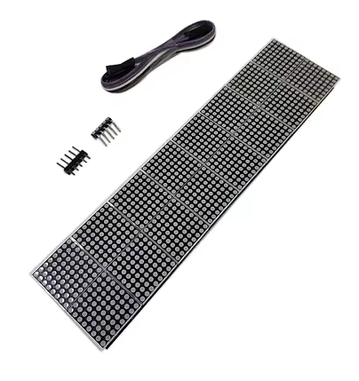
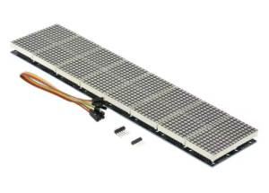
The 2×8-Bit MAX7219 Dot Matrix Module is a high-resolution, large-scale LED display solution that combines sixteen individual 8×8 dot matrix units into a single extended display panel. This module integrates sixteen 1088AS common cathode red LED matrices arranged in a 2×8 configuration, creating a massive combined display area of 16 rows by 64 columns (16×64 pixels) – totaling an impressive 1,024 individually addressable red LEDs. This makes it the ideal choice for high-impact, wide-format scrolling text displays, complex animations, real-time data visualization, and large-scale information signage .
This module is specifically designed for single-chip microcomputer (MCU) control applications, offering a convenient and space-efficient way to add extensive visual output to your embedded projects without complex wiring or multiplexing code. Whether you need to build a large scrolling message board for retail signage, a real-time data display for IoT projects, a sports scoreboard, industrial status indicators, or dynamic visual output for your next electronics project, this 2×8-bit module provides exceptional resolution for sophisticated display needs.
At the heart of this module are MAX7219 integrated circuit drivers – one driver per 8×8 matrix in a cascaded configuration. The MAX7219 is a specialized serial input/output common-cathode display driver that dramatically simplifies the process of controlling LED matrices . It handles all the complex multiplexing and refresh timing internally, eliminating the need for constant microcontroller intervention and ensuring flicker-free display performance. The driver includes an 8×8 static RAM for storing display data, a BCD decoder, a multiplex scan circuit, and segment drivers—all integrated into a single chip .
The module communicates via a simple 3-wire or 4-wire SPI interface (VCC, GND, DIN, CS, CLK), requiring only three I/O pins from your microcontroller to control all 1,024 LEDs. This efficient communication protocol allows the module to be easily integrated with popular development platforms including Arduino, ESP32, ESP8266, STM32, 8051, AVR, PIC, Raspberry Pi, and other SPI-compatible microcontrollers. The module also features input and output headers on opposite sides, allowing multiple units to be cascaded in a daisy-chain configuration to create even larger displays.
Key design benefits include:
-
Flicker-free operation – The MAX7219 automatically refreshes the display at high frequency (approximately 800 Hz)
-
Software-controlled brightness – 16 discrete brightness levels from 0 to 15
-
Low microcontroller overhead – SPI communication minimizes CPU usage
-
16-in-1 compact design – Sixteen 8×8 modules pre-assembled into 16×64 resolution
-
2×8 physical configuration – Two rows of eight modules provides a more natural aspect ratio for wide messaging
-
Cascading capability – Connect multiple modules to build even larger displays
The module uses 1088AS common cathode red LEDs, providing bright, high-contrast red illumination that is clearly visible in both indoor and well-lit environments. The red color offers excellent visibility and is the most common choice for general-purpose displays. The PCB features mounting holes for secure installation and standard 2.54mm pin headers for easy connection to your development board .
Whether you need to build a large scrolling message board for retail signage, a real-time data display for IoT projects, a scoreboard for sports events, a status indicator for industrial equipment, or want to add dynamic visual output to your next electronics project, this 2×8-Bit MAX7219 dot matrix module delivers reliable, bright, and easy-to-control LED display capability in a space-saving 16×64 configuration.
Key Features
-
16-in-1 Integrated Design – Sixteen 8×8 dot matrix modules pre-assembled into a single 16×64 pixel display panel (1,024 total LEDs)
-
2×8 Physical Configuration – Two rows of eight modules provides a wide-format display ideal for scrolling text
-
MAX7219 Driver Chips – Handles all multiplexing and refresh timing automatically for flicker-free display
-
1088AS Common Cathode LED Matrices – Bright red LEDs with excellent visibility and contrast
-
Simple SPI Interface – Only 3 I/O pins required to control all 1,024 LEDs (DIN, CS, CLK)
-
Software Brightness Control – 16 adjustable brightness levels via register setting (0x0 to 0xF)
-
5V Operating Voltage – Compatible with 5V microcontrollers; 3.3V logic devices may require level shifting
-
Cascadable Design – Input and output headers allow multiple modules to be daisy-chained for larger displays
-
Individual LED Control – Each of the 1,024 LEDs can be addressed independently
-
Library Support – Extensive community libraries available (LedControl, MD_Parola, MD_MAX72XX)
Technical Parameters
Usage Guide
Hardware Overview
The module consists of sixteen 1088AS 8×8 red LED matrix panels arranged in a 2×8 configuration (two rows of eight modules), driven by sixteen MAX7219 ICs in a cascaded configuration. The module features input and output headers allowing multiple units to be cascaded for larger displays .
Component Identification:
-
LED Panels: Sixteen 1088AS 8×8 red LED matrices (16 rows × 64 columns total)
-
MAX7219 ICs: Sixteen driver chips (one per matrix) in cascaded configuration
-
Input Header (5 pins) : Connects to your microcontroller
-
Output Header (5 pins) : For cascading to additional modules
1088AS Common Cathode Information
The 1088AS is a standard 8×8 common cathode red LED matrix . In a common cathode configuration, all LEDs in the same row share a common cathode (negative) connection, while columns provide the anode (positive) connections. This configuration is specifically designed for use with the MAX7219 driver IC . The MAX7219 works by sourcing current to up to 8 anodes (columns) and sinking current from one common cathode (row) at a time, scanning across all rows at high frequency (approximately 800 Hz) to create a flicker-free image .
Important Compatibility Note: The MAX7219 requires common cathode LED matrices. The 1088AS is the correct type for these modules. Using common anode matrices (such as 1088BS) will not work correctly without hardware modifications .
Pinout Description
The module uses a standard 5-pin header (2.54mm pitch) for connections:
Wiring Instructions
Step 1 – Connect to Microcontroller
Arduino Uno/Nano Connection:
ESP32 Connection:
ESP8266 Connection:
Raspberry Pi Connection:
8051/AVR/PIC Single-Chip Microcomputer Connection:
⚠️ Important: For Raspberry Pi and other 3.3V logic devices, the MAX7219 requires 5V power, but the logic signals (DIN, CS, CLK) should ideally be level-shifted from 3.3V to 5V for reliable operation . While some users report success without level shifting, voltage level converters are recommended for production installations.
Step 2 – Power Considerations
-
A single 2×8-bit (16×64) module draws approximately 240-640mA under normal operation
-
Maximum current can reach 2.56A when all 1,024 LEDs are illuminated at full brightness
-
Most microcontroller 5V pins can supply 400-500mA, which is insufficient for this module at higher brightness levels
-
For reliable operation, use an external 5V power supply rated for at least 3A (5A recommended)
-
For cascaded modules, increase the power supply rating accordingly
-
Adding a filter capacitor (100µF or larger) across VCC and GND near the module can improve stability and reduce power supply noise
Step 3 – External Power Supply Wiring (Required)
When using an external power supply:
-
Connect external 5V supply positive to module VCC
-
Connect external 5V supply negative to module GND
-
Connect microcontroller GND to module GND (common ground)
-
Do not connect microcontroller 5V to module VCC when using external power
Cascading Multiple Modules
To create larger displays, connect additional modules in a daisy chain:
-
Connect the output header of the first module to the input header of the second module
-
Match pins: VCC→VCC, GND→GND, DIN→DOUT, CS→CS, CLK→CLK
-
Update the MAX_DEVICES parameter in your code to match the total number of 8×8 units (each 2×8-bit module counts as 16 devices)
Cascading Example:
-
1 module (2×8-bit) = 16×64 pixels (16 devices)
-
2 modules = 16×128 pixels (32 devices)
-
4 modules = 16×256 pixels (64 devices)
Software Setup
Important Note on Hardware Type: If the displayed text appears reversed or upside down, change the HARDWARE_TYPE definition. For 1088AS common cathode matrices, FC16_HW is typically the correct setting :
-
#define HARDWARE_TYPE MD_MAX72XX::FC16_HW (most common for 1088AS matrices)
-
#define HARDWARE_TYPE MD_MAX72XX::PAROLA_HW
-
#define HARDWARE_TYPE MD_MAX72XX::GENERIC_HW
Arduino – LedControl Library
-
Install Library: Open Arduino IDE → Tools → Manage Libraries → Search “LedControl” → Install
-
Basic Initialization Code (for 2×8-bit module as 16 devices) :
#include "LedControl.h"
LedControl lc = LedControl(11, 13, 10, 16);
void setup() {
for (int device = 0; device < 16; device++) {
lc.shutdown(device, false);
lc.setIntensity(device, 4);
lc.clearDisplay(device);
}
}
void loop() {
lc.setLed(0, 0, 0, true);
delay(500);
lc.setLed(0, 0, 0, false);
delay(500);
lc.setLed(15, 7, 7, true);
delay(500);
lc.setLed(15, 7, 7, false);
delay(500);
}
Arduino – MD_Parola Library (Scrolling Text Across 16×64 Display)
For advanced scrolling text effects, install both MD_Parola and MD_MAX72XX libraries:
#include <MD_Parola.h>
#include <MD_MAX72xx.h>
#include <SPI.h>
#define HARDWARE_TYPE MD_MAX72XX::FC16_HW
#define CS_PIN 10
#define MAX_DEVICES 16
MD_Parola display = MD_Parola(HARDWARE_TYPE, CS_PIN, MAX_DEVICES);
void setup() {
display.begin();
display.setIntensity(5);
display.displayClear();
}
void loop() {
display.displayScroll("Hello World!", PA_CENTER, PA_SCROLL_LEFT, 80);
while (!display.displayAnimate()) { }
delay(1000);
}
Physical Layout Mapping
The 2×8-bit module is organized as two rows of eight adjacent 8×8 matrices:
Row 0 (Top Row):
Row 1 (Bottom Row):
Preventing Power-On Glitches
When powering on the module, the MAX7219 may briefly illuminate random LEDs before the microcontroller takes control. To prevent this:
-
Use a pull-down resistor on the CS pin – A 10kΩ resistor to ground can help keep the chip select line low during boot
-
Add a delay in setup() – Ensure the module is fully powered before sending configuration
-
Use an external power switch – Some users implement a MOSFET to power the module only after the microcontroller has booted
Installation Tips
-
Power Supply: Use an external 5V power supply (3A minimum, 5A recommended) for reliable operation
-
Filter Capacitors: Adding a 100µF electrolytic capacitor and a 0.1µF ceramic capacitor across VCC and GND near the module improves stability
-
Mounting: Secure using mounting holes with M3 screws or double-sided tape
-
Ventilation: Ensure adequate airflow around the module, especially when running at full brightness for extended periods
-
Cable Length: Keep SPI wires as short as possible (under 50cm) to prevent signal degradation
-
Level Shifting: For 3.3V microcontrollers, use a 4-channel bi-directional logic level converter
-
Enclosure: For outdoor installations, protect the module in a weatherproof enclosure
-
Initial Brightness: Start with lower brightness (intensity 3-5) during testing to avoid excessive current draw
Q: What does "2×8-Bit" mean in this product name?
“2×8-Bit” refers to the physical configuration of this module – it contains sixteen 8×8 dot matrix units arranged in 2 rows of 8 modules each, creating a combined display of 16×64 pixels. The total number of 8×8 matrices is 16.
Q: What is the difference between common cathode and common anode?
The 1088AS common cathode matrix is specifically designed to work directly with the MAX7219 driver without additional circuitry. The MAX7219 is designed as a common cathode driver
Q: Can I use this module with 3.3V microcontrollers like ESP32 or Raspberry Pi?
The MAX7219 requires 5V power for reliable operation . For 3.3V logic devices:
-
Power: Connect VCC to 5V (from external supply or 5V pin)
-
Signals: Use a logic level converter for DIN, CS, and CLK pins
-
While some users report success without level shifting, it is not recommended for production use
Q: What power supply do I need for this module?
This 2×8-bit module can draw up to 2.56A when all 1,024 LEDs are illuminated at full brightness. Most microcontroller 5V pins cannot supply this much current. An external 5V power supply rated for at least 3A (5A recommended) is required. For cascaded modules, increase the power supply rating accordingly
Q: What library should I use for Arduino?
Three popular libraries are:
-
LedControl: Simple, good for basic patterns and custom animations
-
MD_Parola (with MD_MAX72XX): Advanced scrolling text effects, multiple fonts, and alignment options
-
MaxMatrix: Good for basic matrix control
Q: Why is my text displayed backwards or upside down?
This is a common issue caused by incorrect hardware type definition. Try changing the HARDWARE_TYPE in your code :
#define HARDWARE_TYPE MD_MAX72XX::FC16_HW
#define HARDWARE_TYPE MD_MAX72XX::PAROLA_HW
#define HARDWARE_TYPE MD_MAX72XX::GENERIC_HW
You can also adjust the swapX and swapY parameters in some libraries to fix orientation issues
Q: Can I cascade multiple 2×8-bit modules together?
Yes. Connect the output header of one module to the input header of the next . Each 2×8-bit module contains sixteen 8×8 matrices, so update the MAX_DEVICES parameter to 16 × number_of_modules (e.g., 2 modules = 32 devices).
Q: How do I control the brightness?
Brightness can be adjusted in software using:
-
LedControl: lc.setIntensity(device, value) where value = 0 (min) to 15 (max)
-
MD_Parola: display.setIntensity(value)
The MAX7219 supports 16 discrete brightness levels . Start with a lower brightness (3-5) during testing to avoid excessive current draw.
Q: What is the maximum current draw?
-
Normal operation (typical pattern): approximately 240-640mA
-
All 1,024 LEDs at medium brightness: approximately 1.2-1.6A
-
All 1,024 LEDs at maximum brightness: up to 2.56A
-
For cascaded modules, total current adds: 2 modules could draw over 5A at full brightness
-
Always use an external power supply for this module
Q: Can I use this module for both home and business applications?
Home users: Large scrolling message boards, IoT status displays, clock projects, home automation status indicators, weather information displays, DIY digital signage.
Business users: Retail signage (scrolling promotions), industrial equipment status displays, public transportation information boards, queue management displays, laboratory equipment readouts, production line indicators, scoreboards, airport arrival/departure displays