8×16 LED Dot Matrix Display Board – PH 2.54mm Connector with 4-Pin Dupont Cable (Red/Green/Yellow, 1.2mm Thickness)

SKU: FA2092-2
Operating Voltage

DC 3.3V – 5V

Maximum Power Loss

400 mW

Driving Current

200 mA

Oscillation Frequency

450 KHz

Display Resolution

8 × 16 pixels (128 LEDs)

LED Color Options

Red / Green / Yellow (single color per module)

Communication Protocol

I2C / Two-wire serial interface

Connector Type

PH2.54 4-pin (GND, VCC, SDA, SCL)

PCB Thickness

1.2 mm

Description

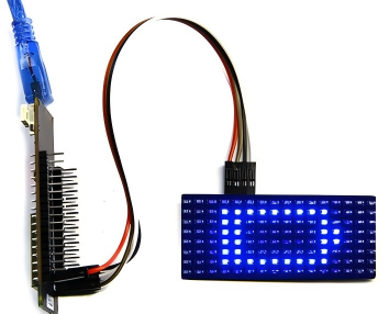
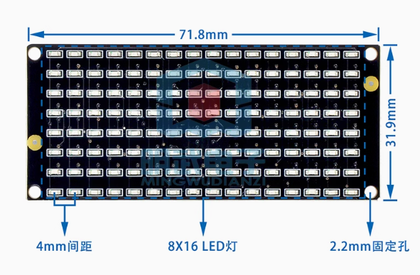
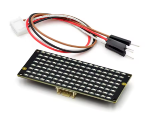
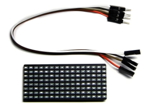
The 8×16 LED Dot Matrix Display Board is a compact and versatile visual output module designed for microcontroller-based projects, electronic signage, and interactive displays. This board features 128 bright LEDs arranged in an 8-row by 16-column grid (8×16 pixels), providing a balanced resolution that is ideal for displaying alphanumeric characters, custom graphics, scrolling text, animations, and real-time data visualizations .

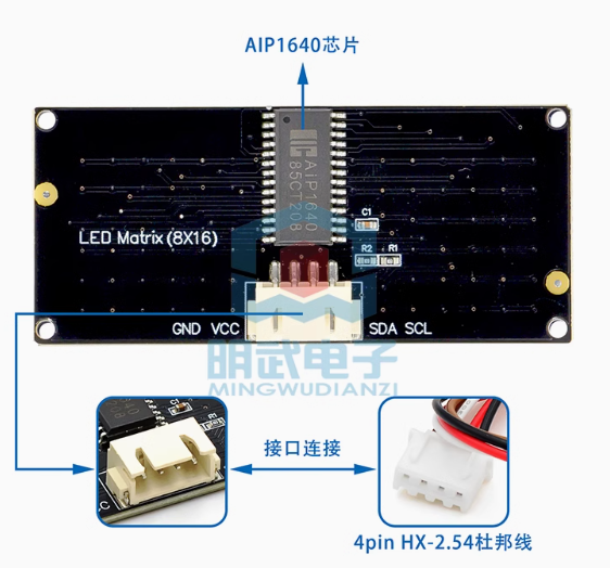
At the heart of this module is the AIP1640 driver chip, which is pre-soldered on the back of the PCB. This dedicated IC handles all the complex multiplexing and refresh timing internally, eliminating the need for constant microcontroller intervention and ensuring flicker-free display performance. The AIP1640 communicates with your microcontroller via a simple I2C-like two-wire interface, requiring only two I/O pins (SCL and SDA) to control all 128 LEDs .

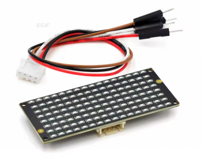
The module includes a standard 4-pin PH2.54 connector and comes with a matching 4-Pin Dupont cable, making it easy to connect to development boards such as Arduino, ESP32, ESP8266, Raspberry Pi, micro:bit, STM32, and 8051-series microcontrollers . The 1.2mm PCB thickness provides durability while maintaining a lightweight form factor.

Color Options: This module is available in three single-color variants—Red, Green, and Yellow. Each variant offers bright, high-contrast illumination suitable for various applications. (Note: This is a single-color display; the color is fixed based on the variant you select.)

The module operates on a wide voltage range of DC 3.3V to 5V, making it compatible with both 3.3V logic (Raspberry Pi, ESP32) and 5V logic (Arduino) systems without requiring level shifters . Four 2.2mm mounting holes at the corners allow for secure installation in enclosures, panels, or custom projects.

Whether you need to build a scrolling message board, create a real-time sensor data display, design a custom scoreboard, add visual feedback to your IoT project, or teach programming concepts in an educational setting, this 8×16 LED Dot Matrix Display Board delivers reliable, bright, and easy-to-control performance in a compact package.

Key Features

  • 128 Individually Controllable LEDs – 8×16 pixel grid for displaying text, numbers, symbols, and custom graphics

  • AIP1640 Driver Chip – Onboard driver handles all multiplexing automatically for flicker-free display

  • Simple 2-Wire Interface – I2C-like communication uses only SCL and SDA pins, saving valuable I/O pins on your microcontroller

  • Wide Voltage Compatibility – Operates on DC 3.3V to 5V, compatible with both 3.3V and 5V logic systems

  • PH2.54 4-Pin Connector – Standard connector with included 4-Pin Dupont cable for easy breadboard and development board connection

  • Single-Color Options – Available in Red, Green, or Yellow high-brightness LEDs

  • Durable Construction – 1.2mm thick PCB with four 2.2mm mounting holes for secure installation

  • Compact Dimensions – Approximately 72mm x 32mm, ideal for space-constrained projects

  • Wide Operating Temperature – -40°C to +80°C, suitable for indoor and protected outdoor applications

  • Extensive Library Support – Compatible with popular Arduino and MicroPython libraries for easy programming

Technical Parameters

Parameter Value
Operating Voltage DC 3.3V – 5V
Maximum Power Loss 400 mW
Driving Current 200 mA
Oscillation Frequency 450 KHz
Display Resolution 8 × 16 pixels (128 LEDs)
LED Color Options Red / Green / Yellow (single color per module)
Communication Protocol I2C / Two-wire serial interface
Connector Type PH2.54 4-pin (GND, VCC, SDA, SCL)
PCB Thickness 1.2 mm

Usage Guide

Hardware Overview

The 8×16 LED Dot Matrix Display Board consists of 128 LEDs arranged in 8 rows and 16 columns, driven by an onboard AIP1640 driver IC located on the back of the PCB. The module uses a 4-pin PH2.54 connector for easy connection to microcontrollers .

Component Identification:

  • Front Side: 8×16 grid of LEDs (128 total)

  • Back Side: AIP1640 driver chip

  • Connector: 4-pin PH2.54 (2.54mm pitch)

  • Mounting Holes: Four 2.2mm diameter holes at corners

Pinout Description

The 4-pin connector uses the following pinout (verify actual labeling on your module; common configurations include) :

Pin Common Label Function Connection
1 GND Ground Connect to common ground with microcontroller
2 VCC Power Supply Connect to 3.3V or 5V DC
3 SDA / DIN Data Line Connect to microcontroller SDA/A4 pin
4 SCL / CLK Clock Line Connect to microcontroller SCL/A5 pin

Note: Pin ordering may vary by manufacturer. Please check the silkscreen labels on your specific module before wiring.

Wiring Instructions

Step 1 – Connect to Microcontroller

The module uses two-wire communication (similar to I2C). Below are common connections:

Arduino Uno/Nano Connection:

Module Pin Arduino Pin
GND GND
VCC 5V
SDA A4 (SDA)
SCL A5 (SCL)

ESP32 Connection:

Module Pin ESP32 Pin
GND GND
VCC 5V or 3.3V
SDA GPIO21 (default SDA)
SCL GPIO22 (default SCL)

Raspberry Pi Connection:

Module Pin Raspberry Pi GPIO (BCM)
GND GND Pin
VCC 5V Pin (or 3.3V)
SDA GPIO2 (SDA)
SCL GPIO3 (SCL)

micro:bit Connection (via expansion board):

Module Pin micro:bit Pin
GND GND
VCC 3V
SDA Pin 20 (SDA)
SCL Pin 19 (SCL)

Step 2 – Power Considerations

  • A single module draws approximately 200mA maximum when all LEDs are illuminated at full brightness

  • Most microcontroller 5V pins can supply sufficient current for one module

  • For multiple modules or high-brightness applications, use an external 5V power supply (rated 1A or higher)

Software Setup

Important Communication Protocol Information:

The AIP1640 chip uses a two-wire interface that is I2C-like but may require specific initialization commands. Below is the general communication flow :

  1. Start Condition: SCL high, SDA transitions from high to low

  2. Command Setting: Send command to configure auto-address increment (typically 0x40)

  3. Address Setting: Set starting address (typically 0xC0)

  4. Data Transmission: Send 16 bytes of pattern data (one byte per column)

  5. End Condition: SCL low, SDA low, then SCL high, SDA high

  6. Display Control: Set brightness/pulse width (typically 0x8A for 4/16 duty cycle)

Arduino – Basic Display Example

This example uses direct I2C communication. For easier implementation, consider using a dedicated library (search for “AIP1640” or “LED Matrix” libraries in the Arduino Library Manager):

cpp
// 8x16 LED Dot Matrix Display with AIP1640 Driver
// Connections: SDA -> A4, SCL -> A5, VCC -> 5V, GND -> GND

#include <Wire.h>

#define SCL_PIN A5
#define SDA_PIN A4

// Smiley face pattern for 8x16 display (16 bytes)
// Each byte represents one column (8 pixels, MSB = top row)
unsigned char smiley[] = {
  0x00, 0x00, 0x1C, 0x02, 0x02, 0x02, 0x5C, 0x40,
  0x40, 0x5C, 0x02, 0x02, 0x02, 0x1C, 0x00, 0x00
};

void setup() {
  pinMode(SCL_PIN, OUTPUT);
  pinMode(SDA_PIN, OUTPUT);
  matrixDisplay(smiley);
}

void loop() {
  // Display stays on
}

void matrixDisplay(unsigned char *pattern) {
  // Start condition
  IIC_Start();
  // Command: Auto address increment (0x40)
  IIC_Send(0x40);
  IIC_End();
  
  // Start condition for data
  IIC_Start();
  // Set starting address to 0xC0
  IIC_Send(0xC0);
  // Send 16 bytes of pattern data
  for (int i = 0; i < 16; i++) {
    IIC_Send(pattern[i]);
  }
  IIC_End();
  
  // Set display brightness (0x8A = 4/16 duty cycle)
  IIC_Start();
  IIC_Send(0x8A);
  IIC_End();
}

void IIC_Start() {
  digitalWrite(SCL_PIN, HIGH);
  delayMicroseconds(3);
  digitalWrite(SDA_PIN, HIGH);
  delayMicroseconds(3);
  digitalWrite(SDA_PIN, LOW);
  delayMicroseconds(3);
}

void IIC_Send(unsigned char data) {
  for (int i = 0; i < 8; i++) {
    digitalWrite(SCL_PIN, LOW);
    delayMicroseconds(3);
    if (data & 0x01) {
      digitalWrite(SDA_PIN, HIGH);
    } else {
      digitalWrite(SDA_PIN, LOW);
    }
    delayMicroseconds(3);
    digitalWrite(SCL_PIN, HIGH);
    delayMicroseconds(3);
    data = data >> 1;
  }
}

void IIC_End() {
  digitalWrite(SCL_PIN, LOW);
  delayMicroseconds(3);
  digitalWrite(SDA_PIN, LOW);
  delayMicroseconds(3);
  digitalWrite(SCL_PIN, HIGH);
  delayMicroseconds(3);
  digitalWrite(SDA_PIN, HIGH);
  delayMicroseconds(3);
}

Creating Custom Patterns with a Modulo Tool:

To create your own patterns, use an online dot matrix modulo tool :

  1. Search for “dot matrix modulo tool” or visit online pattern generators

  2. Set matrix size to 8 (height) × 16 (width)

  3. Click on cells to draw your pattern (left-click = ON, right-click = OFF)

  4. Click “Generate” to obtain hexadecimal data (16 bytes)

  5. Copy the generated array into your code

Important Note on Data Orientation: Depending on your module, the display may show patterns rotated 180 degrees or mirrored. If your pattern appears inverted, you may need to reverse the byte order or bit order. Test with a simple pattern (e.g., a single dot in the corner) to determine correct orientation .

Creating Custom Patterns

The 8×16 display uses 16 bytes of data (one byte per column). Each byte controls one column of 8 LEDs, where the Most Significant Bit (MSB) typically controls the top LED and the Least Significant Bit (LSB) controls the bottom LED .

Example: Heart Pattern for 8×16 Display

cpp
unsigned char heart[] = {
  0x00, 0x00, 0x00, 0x00, 0x00, 0x1C, 0x22, 0x42,
  0x84, 0x42, 0x22, 0x1C, 0x00, 0x00, 0x00, 0x00
};

Binary representation of heart pattern (columns 5-12):

  • Column 5 (0x1C): 00011100 (fourth row from top)

  • Column 6 (0x22): 00100010

  • Column 7 (0x42): 01000010

  • Column 8 (0x84): 10000100

  • Column 9 (0x42): 01000010

  • Column 10 (0x22): 00100010

  • Column 11 (0x1C): 00011100

Multiple Module Cascading

Some versions of this module support cascading multiple units to create larger displays. To cascade:

  1. Connect the output pins of the first module to the input pins of the second module

  2. Match VCC, GND, SDA, and SCL

  3. Address configuration may vary; check your specific module documentation

Installation Tips

  • Mounting: Secure using M2.2 screws through the four corner mounting holes

  • Ventilation: Ensure adequate airflow around the module, especially in high-brightness applications

  • Cable Length: Keep I2C wires under 50cm to prevent signal degradation

  • Pull-up Resistors: Some modules have onboard pull-up resistors for SDA and SCL; if not, add 4.7kΩ resistors to VCC

  • Enclosure: For outdoor or dusty environments, protect the module in a weatherproof enclosure with a transparent window

  • Multiple Modules: When using multiple I2C devices, ensure unique addresses or use an I2C multiplexer

Q: What is the difference between the Red, Green, and Yellow versions?

The only difference is the LED color. All electrical specifications and communication protocols are identical across all three color variants. Choose based on your visual preference and application requirements:

  • Red: Classic display color; excellent visibility; lower power consumption typically

  • Green: High human eye sensitivity; good visibility in various lighting conditions

  • Yellow: Good contrast; often used for warning or attention-grabbing displays

Q: Does this module work with Arduino?

Yes, this module is fully compatible with Arduino (Uno, Nano, Mega, Leonardo, etc.). Connect VCC to 5V, GND to GND, SDA to A4, and SCL to A5. Use the provided example code or search for AIP1640/HT16K33 libraries for easier implementation

Q: Can I use this module with Raspberry Pi?

Yes. The module’s 3.3V-5V operating voltage range allows direct connection to Raspberry Pi’s 3.3V logic. Connect VCC to 3.3V or 5V pin, GND to GND, SDA to GPIO2, and SCL to GPIO3. Use Python with the smbus or adafruit-circuitpython libraries for control.

Q: Does this module work with micro:bit?

Yes, this module is compatible with BBC micro:bit. Connect via an expansion board’s I2C port (typically pins 19 and 20 for SCL and SDA) . Some MakeCode extensions provide dedicated blocks for 8×16 matrix control.

Q: What is the difference between this module and one with a MAX7219 driver?
Feature AIP1640 Module (This) MAX7219 Module
Communication 2-wire (I2C-like) 3-wire (SPI)
I/O Pins Required 2 pins (SDA, SCL) 3 pins (DIN, CS, CLK)
Cascading Limited (address config) Easy (daisy chain)
Typical Use Simple, pin-efficient projects Larger displays, cascading

Both are excellent choices; this module is ideal when I/O pins are limited.

Q: What is the maximum current draw?

The module draws approximately 200mA maximum when all 128 LEDs are illuminated at full brightness . Normal operation with typical patterns draws significantly less (20-80mA). For battery-powered projects, consider using lower brightness settings.

Q: Can I cascade multiple modules together?

Some versions of this module support cascading by connecting the output of one module to the input of another. However, cascading capability varies by manufacturer. For large displays, MAX7219-based modules may be more suitable. Check your specific product documentation for cascading support.

Q: Can I use this module for both home and business applications?

Home users: DIY message boards, IoT status displays, clock projects, home automation indicators, retro game displays, custom scoreboards, weather information displays.

Business users: Retail signage (scrolling promotions), industrial equipment status displays, queue management displays, laboratory equipment readouts, small public information boards, production line indicators.

Q: Does the module remember the display content after power loss?

No. The AIP1640 has volatile memory. When power is lost, the display content is cleared. Your microcontroller must re-send display data during startup.

Q: How do I create custom patterns?

Use an online dot matrix modulo tool :

  1. Set matrix dimensions to 8 (height) × 16 (width)

  2. Click cells to draw your pattern

  3. Click “Generate” to obtain 16 bytes of hexadecimal data

  4. Copy the generated array into your code

Test with a simple pattern first to verify orientation.