Description
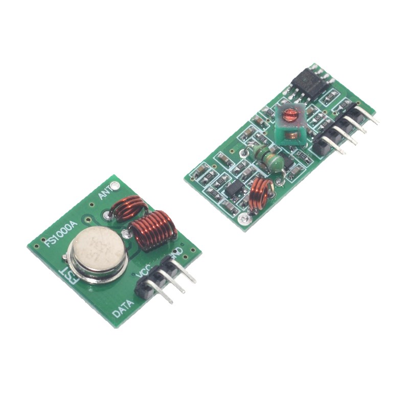
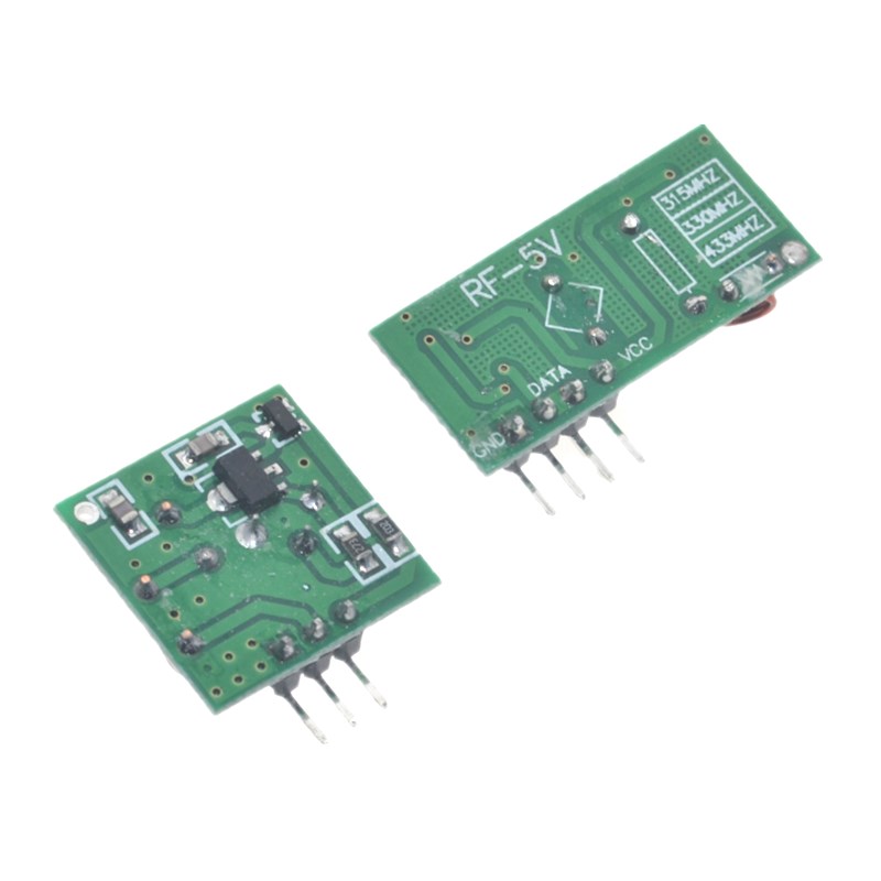
The Wireless RF Link Kit – 433MHz Transmitter & Receiver Set is a cost-effective, easy-to-use wireless communication solution designed for microcontroller projects, remote control systems, and wireless data transmission applications. Operating in the 433MHz ISM (Industrial, Scientific, and Medical) band, this module pair enables reliable wireless communication between devices over distances of up to 100-300 meters in open areas, making it an ideal choice for projects where running wires is impractical or impossible .
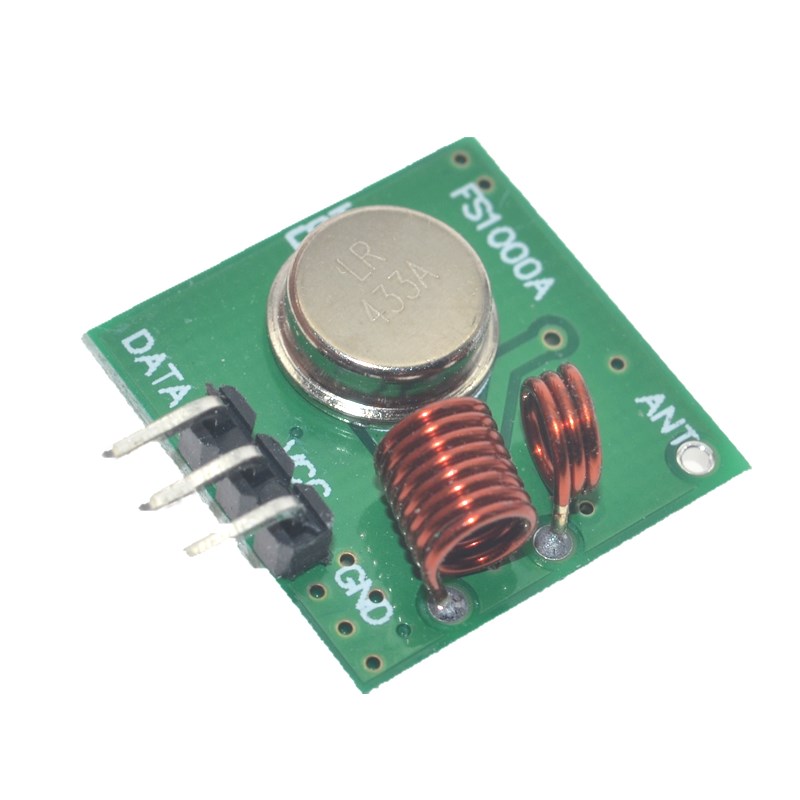
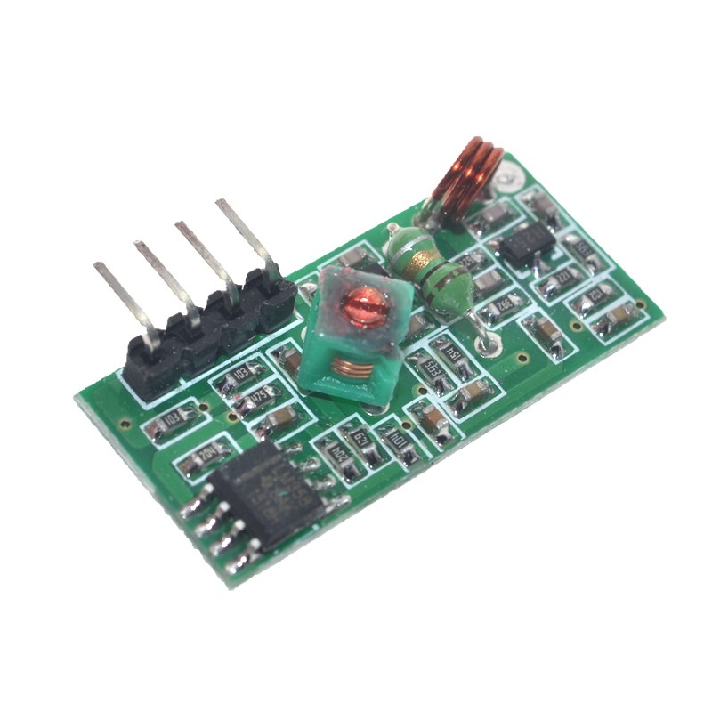
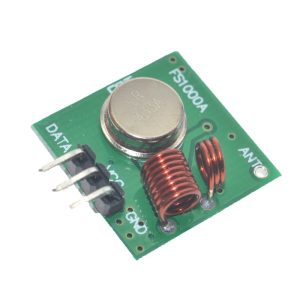
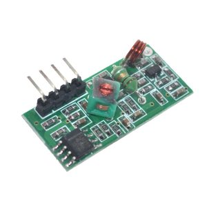
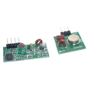
The kit includes two separate modules: a transmitter and a receiver. The transmitter accepts digital data signals from a microcontroller or switch and transmits them over the air via ASK (Amplitude Shift Keying) or OOK (On-Off Keying) modulation . The receiver captures these signals and outputs the corresponding digital data, allowing the receiving microcontroller or circuit to act upon the information.
These modules are incredibly simple to use, requiring no complex configuration or frequency setup. They communicate via a straightforward logic-level serial data stream, making them compatible with virtually any microcontroller, including Arduino, ESP32, ESP8266, STM32, Raspberry Pi, PIC, and 8051 series devices . The transmitter and receiver are sold as a matched pair, pre-tuned to the same frequency for plug-and-play operation.
Key advantages of RF communication include:
-
Penetration through walls – RF signals can pass through common building materials like drywall, brick, and wood, unlike IR (infrared) which requires line-of-sight
-
Low power consumption – Suitable for battery-powered applications and portable devices
-
Simple encoding/decoding – Can be used with software libraries like VirtualWire, RadioHead, or Manchester coding
-
No line-of-sight required – Signals can travel around corners and through obstacles
-
Cost-effective – One of the most affordable wireless solutions available
The transmitter and receiver modules come as bare boards with pin headers for easy breadboard or PCB integration. The receiver typically includes an onboard LED to indicate power and signal reception, and both modules feature an antenna pin for connecting a wire antenna (typically a 17-25cm straight wire for optimal performance at 433MHz) .
Whether you need to build a wireless remote control, a remote sensor monitoring system, a wireless doorbell, a garage door opener, a home automation controller, or a simple data link between two microcontrollers, this 433MHz RF Link Kit provides a simple, reliable, and affordable wireless solution.
Key Features
-
433MHz Operating Frequency – Operates in the license-free ISM band, no registration required for low-power applications
-
ASK/OOK Modulation – Simple modulation scheme for easy integration with microcontrollers and logic circuits
-
Long Transmission Range – Up to 100-300 meters in open areas (with proper antenna and line-of-sight)
-
Low Power Consumption – Transmitter typically draws 3-12mA, receiver 3-5mA at 3-5V operation
-
Wide Operating Voltage – Transmitter: 3V-12V DC; Receiver: 3V-5V DC (check specific module specifications)
-
Simple Digital Interface – Single data pin for serial communication with any microcontroller or logic circuit
-
Easy Antenna Connection – Onboard antenna pad for connecting a simple wire antenna (recommended length: 17-25cm)
-
Compact Form Factor – Small module size for easy integration into portable devices and enclosures
-
Compatible with Popular Libraries – Works with RadioHead, VirtualWire, and Manchester coding libraries
-
Plug-and-Play Operation – No configuration or programming required; modules work as soon as power is applied
Technical Parameters
Usage Guide
How It Works
The 433MHz RF modules use ASK (Amplitude Shift Keying) modulation to transmit digital data. When the transmitter’s DATA pin is HIGH, the module transmits a carrier signal at 433.92MHz. When the DATA pin is LOW, the carrier is off. The receiver detects the presence or absence of this carrier signal and outputs a corresponding HIGH or LOW logic level . This simple on-off keying makes the modules easy to interface with microcontrollers.
Important Note: These modules do not encode or decode data. They simply transmit and receive raw logic levels. For reliable communication, you must implement some form of encoding in your software, such as Manchester coding, or use a library like RadioHead or VirtualWire .
Pinout Description
Transmitter (TX) Pinout:
Receiver (RX) Pinout:
Note: Pin arrangements may vary by manufacturer. Always check the silkscreen on your specific module before wiring.
Wiring Instructions
Step 1 – Basic Connection (Arduino Example)
Transmitter Side Wiring:
Receiver Side Wiring:
Step 2 – Install Required Libraries
For Arduino, install the RadioHead library (recommended for reliable operation) :
-
Open Arduino IDE
-
Go to Sketch → Include Library → Manage Libraries
-
Search for “RadioHead”
-
Install the library by AirSpayce
Software Setup
Simple RadioHead ASK Example (Transmitter)
#include <RH_ASK.h>
#include <SPI.h>
RH_ASK rf_driver(2000, 12, 13);
void setup() {
Serial.begin(9600);
if (!rf_driver.init()) {
Serial.println("RF driver init failed");
}
}
void loop() {
const char *msg = "Hello World!";
rf_driver.send((uint8_t *)msg, strlen(msg));
rf_driver.waitPacketSent();
Serial.println("Message sent");
delay(1000);
}
Simple RadioHead ASK Example (Receiver)
#include <RH_ASK.h>
#include <SPI.h>
RH_ASK rf_driver(2000, 11, 12);
void setup() {
Serial.begin(9600);
if (!rf_driver.init()) {
Serial.println("RF driver init failed");
}
}
void loop() {
uint8_t buf[RH_ASK_MAX_MESSAGE_LEN];
uint8_t buflen = sizeof(buf);
if (rf_driver.recv(buf, &buflen)) {
Serial.print("Received: ");
Serial.println((char*)buf);
}
}
Simple Encoding Without Library (Manchester Example)
For basic applications, you can implement your own simple encoding:
void sendBit(bool bit) {
digitalWrite(TX_PIN, bit ? HIGH : LOW);
delay(2);
digitalWrite(TX_PIN, LOW);
delay(2);
}
void sendByte(uint8_t data) {
for (int i = 0; i < 8; i++) {
sendBit(bitRead(data, i));
}
}
Antenna Installation
A proper antenna is critical for achieving maximum range :
-
Simple wire antenna: Cut a single-strand copper wire to 17-25cm (approximately 1/4 wavelength of 433MHz)
-
Spring antenna: Some modules include a coiled spring antenna – extend it straight for best performance
-
SMA antenna: For maximum range, use an external SMA antenna with proper impedance matching
-
Antenna placement: Keep the antenna straight, away from metal surfaces, and vertically oriented
Troubleshooting Communication Failures
If your modules are not communicating, check these common issues :
-
Power supply issues: Ensure stable voltage (3-5V for receiver, 3-12V for transmitter). Power supply noise can cause intermittent operation
-
Antenna not connected: Even a short 10cm wire is better than no antenna. A proper 17-25cm antenna is strongly recommended
-
Modules too close: Place transmitter and receiver at least 1 meter apart during testing – direct coupling can overload the receiver
-
Baud rate mismatch: Ensure both modules are configured for the same data rate (typically ≤ 10Kbps)
-
No encoding: Raw data transmission without any encoding or start bits is unreliable; use the RadioHead library for best results
Range Optimization Tips
-
Use a proper antenna – A 17-25cm straight wire is the minimum; external antennas can improve range significantly
-
Elevate the modules – Higher mounting positions reduce ground reflection and interference
-
Avoid metal obstacles – Metal structures and reinforced concrete significantly reduce signal strength
-
Reduce data rate – Lower baud rates (e.g., 1200-2400 bps) provide better sensitivity and longer range
-
Add a filter capacitor – A 100µF capacitor across VCC and GND near the modules can reduce power supply noise
Typical Applications
Q: What is the maximum range of these modules?
The typical range is up to 100 meters indoors and up to 300 meters in open areas with clear line-of-sight . Actual range depends on environmental factors such as walls, metal obstacles, electrical interference, antenna quality, and power supply stability. For maximum range, use a proper antenna (17-25cm wire) and keep the modules elevated.
Q: Can I use this module with 3.3V microcontrollers like ESP32 or Raspberry Pi?
Yes, but with caution. The receiver can operate at 3.3V (typical range 3-5V). However, the transmitter’s performance varies with voltage – at 3.3V, transmission power and range will be reduced compared to 5V or 12V operation . For best results with 3.3V systems, power the transmitter with 5-12V (from an external supply) and only connect the DATA pin to the 3.3V microcontroller output. Use a voltage divider for the receiver’s DATA output if connecting to a 3.3V input.
Q: What is the maximum data rate?
The modules typically support data rates up to 10 Kbps . For reliable communication, it is recommended to use lower data rates (e.g., 1200-2400 bps), especially when using simple encoding schemes without error correction. The RadioHead library defaults to 2000 bps for good reliability.
Q: Why are my modules not communicating?
Most common issues and solutions :
-
Power supply: Check voltage levels and add a 100µF capacitor across VCC/GND to filter noise
-
Antenna: Ensure a proper antenna (17-25cm wire) is connected
-
Modules too close: Move them at least 1 meter apart – direct proximity can overload the receiver
-
Data rate mismatch: Ensure transmitter and receiver are configured for the same baud rate
-
No encoding: Use a library like RadioHead to implement proper packet encoding
-
Interference: Other 433MHz devices (garage door openers, weather stations) may cause interference; try changing location
Q: Can I use multiple transmitters with one receiver?
Yes, with proper protocol implementation. The receiver can receive data from multiple transmitters if you implement addressing in your software. Each transmitter must have a unique identifier in its data packets. The receiver can then distinguish between different sources. Note that if multiple transmitters transmit simultaneously, packet collisions will occur, so you must implement a collision avoidance or retransmission protocol.
Q: Do I need an external antenna?
While the modules can work without an external antenna over very short distances (a few meters), an antenna is strongly recommended for reliable operation. A simple 17-25cm straight copper wire soldered to the ANT pad is sufficient for most applications . For maximum range, use a tuned 433MHz antenna (spring antenna or SMA external antenna).
Q: What is the difference between ASK and FSK modulation?
This module uses ASK (Amplitude Shift Keying) or OOK (On-Off Keying) – a simple modulation where the carrier is either ON (transmitting) or OFF (not transmitting). ASK is simple and low-cost but more susceptible to interference. FSK (Frequency Shift Keying) uses frequency changes to represent data and is more immune to noise but requires more complex hardware. For most hobbyist applications, ASK modules are perfectly adequate and significantly more affordable.
Q: Can I use this module for both home and business applications?
Home users: Wireless remote controls, DIY home automation, garage door openers, wireless doorbells, remote garden watering systems, pet feeder triggers, wireless temperature/humidity monitors, toy remote controls, holiday light controllers.
Business users: Remote industrial sensor monitoring, wireless status indicators, inventory tracking systems, wireless data collection from remote equipment, parking lot occupancy sensors, wireless alert systems, access control triggers, agricultural sensor networks, and prototype development for commercial wireless products.
Q: How do I prevent interference from other 433MHz devices?
433MHz is a shared ISM band used by many devices including garage door openers, weather stations, tire pressure monitoring systems, and other remote controls . To minimize interference:
-
Use error detection (CRC checksums) and retransmission in your protocol
-
Implement unique packet headers or preamble patterns to identify your data
-
Use Manchester encoding which has better noise immunity than raw data
-
Add filtering (hardware or software) to ignore short noise pulses
-
Consider using modules with FSK modulation or frequency hopping for more robust communication
Q: What is included in the package?
-
1 x 433MHz RF Transmitter Module
-
1 x 433MHz RF Receiver Module
-
(Antenna wire may or may not be included depending on the specific kit)