Description
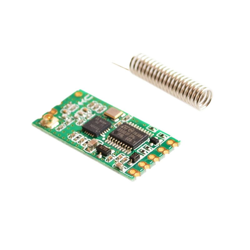
The HC-11 433MHz Wireless RF Serial UART Module is a low-cost, high-performance FSK (Frequency Shift Keying) transceiver module designed for transparent wireless serial communication. Built around the popular CC1101 RF chip, this module is an excellent replacement for Bluetooth modules in many applications, offering longer range and more robust performance in challenging environments .
Unlike simple ASK (Amplitude Shift Keying) modules, the HC-11 uses FSK modulation, which provides superior noise immunity and more reliable data transmission . The module operates as a complete wireless serial link – data sent into the UART port of one module is automatically transmitted wirelessly and appears at the UART port of any other HC-11 module on the same channel. No additional RF programming or protocol handling is required by your microcontroller .
The HC-11 features a built-in MCU that handles all RF protocol processing internally. This means you simply connect the module to your microcontroller’s UART pins (TX and RX), and it functions just like a wired serial connection – but without the wires. The module supports a wide range of UART baud rates from 1200 bps to 115200 bps, making it compatible with virtually any microcontroller .
Multiple Operating Modes: The HC-11 offers four UART transparent transmission modes (FU1-FU4), allowing you to optimize for power consumption or speed:
Configuration Flexibility: All module parameters are configurable via simple AT commands, including communication channel (001-127), UART baud rate, transmit power (8 levels), and operating mode. Settings are stored in non-volatile memory and retained after power loss .
Important Note: The HC-11 is not compatible with the HC-12 module . These two modules operate on different protocols and cannot communicate with each other. For best results, use HC-11 modules in pairs or multiples.
Whether you need to create a wireless sensor network, replace a wired serial connection between two microcontrollers, add remote control to a project, or build a wireless data logging system, the HC-11 provides a simple, reliable, and affordable wireless serial solution.
Key Features
-
433MHz FSK Transceiver – Built on CC1101 chip, provides reliable, noise-immune wireless communication
-
Transparent Serial Communication – No RF programming needed; data in = data out wirelessly
-
Multiple Operating Modes – Four modes (FU1-FU4) with idle currents of 80µA, 3.5mA, or 22mA for power optimization
-
Wide Baud Rate Support – UART speeds from 1200 bps to 115200 bps (default 9600 bps)
-
AT Command Configuration – Set channel, baud rate, power level, and mode via simple text commands
-
Adjustable Transmit Power – 8 power levels from -30dBm to +10dBm (10mW max)
-
Wide Voltage Range – Operates from 3.3V to 5V DC, compatible with both 3.3V and 5V microcontrollers
-
Multiple Channels – 20+ selectable channels (001-127) with 400KHz step spacing
-
Compact Form Factor – 27.8mm × 14.4mm × 4mm with 2.54mm pin headers
-
Wide Temperature Range – -40°C to +85°C for industrial applications
Technical Parameters
Usage Guide
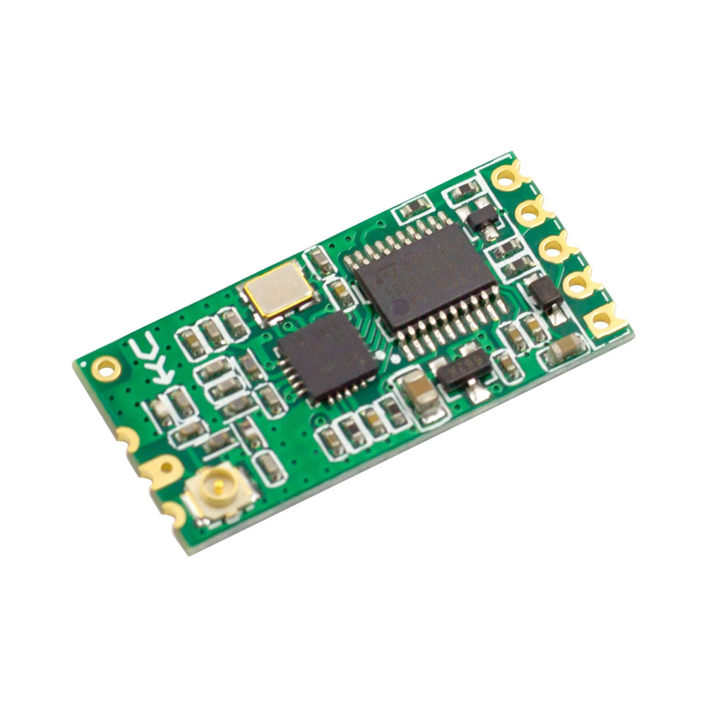
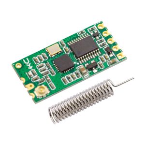
Hardware Overview
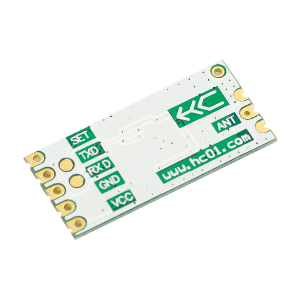
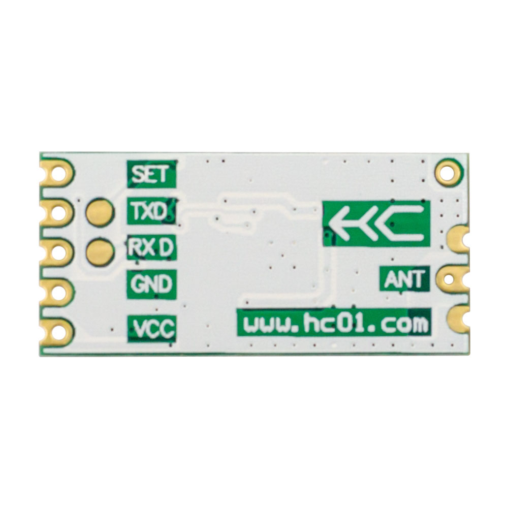
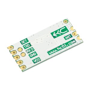
The HC-11 module features 9 pins, with the first 5 pins (1-5) typically used for standard 2.54mm header connection. The module includes both a UART interface for serial communication and a SET pin for entering command mode .
Key Components:
-
CC1101 RF Chip – Handles all wireless transmission and reception
-
Onboard MCU – Manages UART communication and AT command processing
-
ANT1 / ANT2 – Antenna connection points (spring antenna or external SMA)
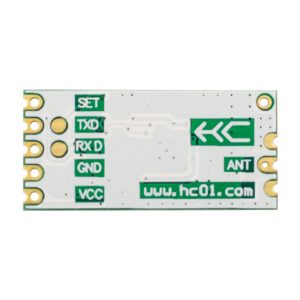
Pinout Description
The HC-11 module uses the following pin configuration :
Wiring Instructions
Basic Connection (Microcontroller to HC-11):
Important: When connecting two HC-11 modules to communicate with each other, connect:
Antenna Connection:
AT Command Configuration
Entering AT Command Mode:
There are two methods to enter AT command mode :
-
Method 1 (Normal Operation): While the module is powered on and operating normally, pull the SET pin LOW. The module will enter command mode. Release SET to exit.
-
Method 2 (Power-on): Pull SET pin LOW before applying power, then power on the module. After 1 second, the module enters command mode. Release SET to exit.
Important Notes for AT Commands:
-
In command mode, the UART format is fixed at 9600 bps, 8 data bits, no parity, 1 stop bit
-
Commands must be sent in uppercase
-
Each command must be terminated with \r\n (carriage return + line feed)
-
Characters within a command must be sent in quick succession
Available AT Commands :
Supported Baud Rates: 1200, 2400, 4800, 9600, 19200, 38400, 57600, 115200 bps
Channel Frequency Mapping:
-
Channel 001: 434.4 MHz
-
Channel 002: 434.8 MHz
-
…
-
Channel 020: 439.0 MHz
Transmit Power Levels :
Operating Modes (FU1-FU4)
Arduino Example Code
Basic Serial Passthrough (Transparent Mode – No Code Required)
The HC-11 works in transparent mode by default. Simply connect the module to your Arduino’s hardware serial pins, and any data sent to Serial will be transmitted wirelessly to another HC-11 module.
#include <SoftwareSerial.h>
SoftwareSerial hc11(10, 11);
void setup() {
Serial.begin(9600);
hc11.begin(9600);
Serial.println("HC-11 Wireless Serial Ready");
}
void loop() {
if (Serial.available()) {
hc11.write(Serial.read());
}
if (hc11.available()) {
Serial.write(hc11.read());
}
}
Sending AT Commands from Arduino:
#include <SoftwareSerial.h>
SoftwareSerial hc11(10, 11);
void setup() {
Serial.begin(9600);
hc11.begin(9600);
pinMode(9, OUTPUT);
digitalWrite(9, LOW);
delay(100);
hc11.println("AT");
delay(500);
hc11.println("AT+V");
delay(500);
while (hc11.available()) {
Serial.write(hc11.read());
}
digitalWrite(9, HIGH);
}
void loop() {
}
Range Optimization Tips
-
Use a proper antenna – A spring antenna or 17-20cm wire significantly improves range
-
Select FU3 or FU4 mode – These modes provide better range at lower baud rates
-
Lower the baud rate – Slower data rates improve receiving sensitivity and range
-
Increase transmit power – Use AT+P8 for maximum power (+10dBm)
-
Avoid metal enclosures – Metal significantly attenuates RF signals
-
Keep modules at least 1 meter apart – Direct proximity can overload the receiver
Important Compatibility Note
HC-11 cannot communicate with HC-12 modules . These two modules use different protocols and are not interoperable. For wireless communication, all modules in your network must be HC-11 modules.
Q: What is the difference between HC-11 and HC-12?
The HC-11 and HC-12 are different modules and are not compatible with each other . Key differences:
-
HC-11: Shorter range (1-40m), lower power consumption (as low as 80µA idle), FSK modulation
-
HC-12: Longer range (up to 1000m), higher power consumption, different protocol
For most indoor and short-range applications, HC-11 is the better choice due to its lower power consumption.
Q: What is the maximum communication distance?
In typical indoor environments, the HC-11 provides reliable communication from 1 to 40 meters . Note that the modules cannot communicate reliably at distances less than 1 meter due to receiver overload . For maximum range, use FU3 or FU4 mode, lower baud rates, and proper antennas.
Q: Why can't I get into AT command mode?
Common issues and solutions :
-
Check baud rate: In command mode, the UART is fixed at 9600 bps, 8 data bits, no parity, 1 stop bit
-
Send commands quickly: All characters in a command must be sent in quick succession
-
Use proper line endings: Commands must end with \r\n (carriage return + line feed)
-
Check SET pin connection: Ensure SET pin is pulled LOW (connected to GND) to enter command mode
-
Try power-on method: Pull SET LOW before applying power, then power on
Q: Can I use this module with 3.3V microcontrollers (ESP32, Raspberry Pi, STM32)?
Yes. The HC-11 operates from 3.3V to 5.5V, making it directly compatible with both 3.3V and 5V logic systems . Connect VCC to 3.3V for lower power consumption.
Q: What is the default configuration?
| Parameter |
Default Setting |
| Operating Mode |
FU1 |
| UART Baud Rate |
9600 bps |
| RF Channel |
001 (434.4 MHz) |
| Module Address |
000 |
| Transmit Power |
P8 (+10dBm, maximum) |
Q: What is the difference between FU1, FU2, FU3, and FU4 modes?
| Mode |
Idle Current |
Best For |
| FU1 |
~3.5mA |
General purpose, balanced power and speed (default) |
| FU2 |
~80µA |
Battery-powered devices, low data rate |
| FU3 |
~22mA |
Low latency, high-speed communication |
| FU4 |
~22mA |
Extended range (lower baud rate = longer range) |
Q: Can I use multiple HC-11 modules in the same area?
Yes. By setting different RF channels (AT+Cxxx command), you can have multiple independent wireless networks operating in the same area without interference. The module supports channels 001-127
Q: Can I use this module for both home and business applications?
Home users: Wireless sensor networks, remote temperature monitoring, garden irrigation control, wireless Arduino projects, replacing Bluetooth for longer range.
Business users: Industrial data collection, remote equipment monitoring, wireless sensor networks, building automation, prototype development for commercial wireless products.
Q: Does the module save settings after power loss?
Yes. All configuration settings (baud rate, channel, address, mode, power level) are stored in non-volatile memory and retained after power loss
Q: What is the difference between FSK and ASK modulation?
FSK (Frequency Shift Keying) – Used by HC-11 – changes frequency to represent data. Provides better noise immunity and more reliable communication in noisy environments .
ASK (Amplitude Shift Keying) – Used by simpler modules – changes signal strength to represent data. More susceptible to interference.
HC-11’s FSK modulation makes it more reliable than basic ASK modules.