Description
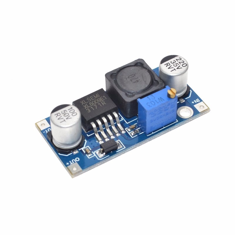
The XL6009 4A Adjustable Boost Converter Module is a high-performance DC-DC step-up (boost) switching regulator designed to efficiently elevate lower DC voltages to higher, adjustable output levels. As a superior alternative to older LM2577-based modules, the XL6009 is engineered for demanding applications that require higher power, greater efficiency, and more compact design.
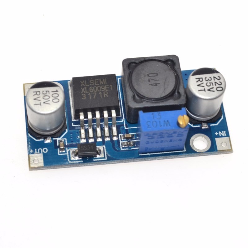
At the heart of this module is the XL6009E1 chip, a second-generation high-frequency switching regulator that integrates a high-current 4A MOSFET switch. This advanced design allows the module to deliver up to 4A of peak output current (approximately 2A-3A continuous with proper cooling) while maintaining excellent conversion efficiency of up to 94% .
Wide Operating Range & Superior Performance:
The XL6009 operates from a wide input voltage range of 3V to 32V (optimal range: 5V-32V) and provides an adjustable output from 1.25V up to 35V (or higher, depending on the specific module version) . Whether you need to boost a 3.7V lithium battery to 5V for USB charging, convert 12V to 24V for industrial equipment, or stabilize automotive power fluctuations, the XL6009 delivers reliable, clean power.
Technical Advantages over LM2577:
The XL6009’s 400KHz switching frequency is a significant upgrade over the LM2577’s 50KHz. This higher frequency allows for the use of smaller, lower-cost filter capacitors while achieving lower output ripple and a more compact module design .
Key Applications:
-
Automotive Voltage Regulation: Stabilizes vehicle electrical systems where voltage can fluctuate between 5V and 32V, maintaining a steady 12V output
-
Solar and Wind Power Systems: Converts variable renewable energy sources to stable voltages for battery charging or equipment power
-
Portable Electronics: Boosts single-cell lithium batteries (3.7V) to 5V, 9V, or 12V for powering microcontrollers, LED strips, and other devices
-
LED Lighting: Drives high-power LED arrays with adjustable constant-voltage output
-
Industrial Equipment: Provides higher voltage rails for sensors, actuators, and control systems
Important Operating Note: This module is a step-up (boost) converter only. The output voltage must be set higher than the input voltage for proper regulation. If the input exceeds the set output, the module cannot step down, and the output will approximately follow the input, potentially damaging your load.
Whether you are an electronics hobbyist, an IoT developer, or an industrial engineer, the XL6009 4A Boost Converter Module provides a powerful, efficient, and reliable solution for all your voltage boosting needs.
Key Features
-
Wide Input Voltage Range – Accepts DC 3V to 32V input (optimal 5V-32V), compatible with single-cell Li-Ion batteries, USB (5V), car electrical systems, and various power supplies
-
Wide Adjustable Output – Output can be set from 5V up to 35V (some versions up to 60V) via onboard precision potentiometer
-
4A Peak Output Current – Integrated 4A MOSFET switch delivers up to 4A peak (2A-3A continuous recommended with heatsink)
-
High Conversion Efficiency – Up to 94% efficiency minimizes power loss and heat generation, outperforming LM2577 modules
-
400KHz High Switching Frequency – Enables smaller filter capacitors, lower output ripple (30-50mV), and compact module design
-
Excellent Regulation – Load regulation of ±0.5% and voltage regulation of ±0.5% ensure stable output under varying conditions
-
Built-in Protection – Integrated over-temperature and over-current protection for safe, reliable operation
-
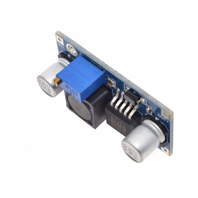
Simple Adjustment – Multi-turn potentiometer allows precise voltage tuning with a small screwdriver (may require 10-15 turns initially)
-
Wide Operating Temperature – -40°C to +85°C for reliable operation in automotive, industrial, and outdoor environments
-
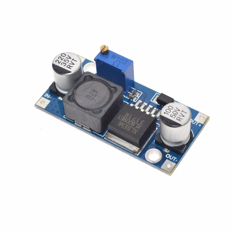
Compact Form Factor – Small footprint (approx. 43mm × 21mm × 14mm) with clearly labeled input/output pads
Technical Parameters
Usage Guide
Pinout Description
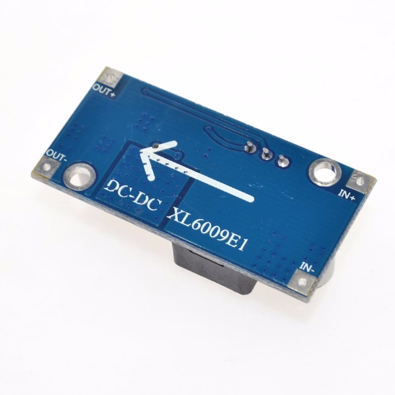
The module features four clearly labeled solder pads:
Note: Input and output grounds are common (connected together on the board) .
Wiring Instructions
Step 1 – Connect Input Power
-
Connect IN+ to the positive terminal of your DC power source (battery, power supply, solar panel, etc.)
-
Connect IN- to the negative terminal of your DC power source
Step 2 – Connect Load
Step 3 – Adjust Output Voltage
-
Power the module with your input source
-
Use a digital multimeter to measure voltage between OUT+ and OUT-
-
Turn the blue potentiometer with a small screwdriver:
Critical Adjustment Note – The “Endless Turn” Issue
This is the most common point of confusion for new users. The potentiometer often ships at its maximum resistance position. If you turn the screw and see no voltage change, you need to turn it counter-clockwise for 10-15 full rotations before the voltage begins to increase . Keep turning while watching your multimeter until the voltage starts to rise. The potentiometer is multi-turn, so you won’t damage it by continuing to turn.
Current Limitations and Thermal Management
While the XL6009 chip is rated for 4A peak, practical limitations apply :
Important Current Relationship: Boost converters draw more input current than output current due to power conservation. The relationship is:
Power In × Efficiency = Power Out or VIN × IIN × Efficiency = VOUT × IOUT
Example: To get 1A at 12V output (12W) from a 5V input, the input current must be approximately 2.5A-3A (accounting for efficiency losses) . Ensure your input power source can supply sufficient current.
Heat Management Tips:
-
Add a heatsink to the XL6009 chip for continuous loads above 1.5A
-
Ensure adequate airflow around the module
-
Consider using a higher input voltage to reduce the voltage conversion ratio and associated heat
-
The module will automatically reduce current or shut down if it overheats (thermal protection)
Important Operating Restrictions
Voltage Limitation (Critical):
This module is a step-up (boost) converter only. It CANNOT step down voltage. The output voltage must always be set higher than the input voltage for proper regulation. If the input voltage exceeds the set output voltage, the module will not regulate down, and the output will approximately follow the input voltage (minus a small diode drop), potentially delivering high voltage to your low-voltage load and destroying it.
Reverse Polarity Warning:
This module does NOT have reverse polarity protection. Double-check your IN+ and IN- connections before applying power. Connecting backwards will instantly destroy the module .
No Short Circuit Protection:
Most basic XL6009 modules do not include dedicated short circuit protection. The chip has over-current limiting, but this is not a full protection feature. Adding a small fuse on the input line is good safety practice.
Real-World Power Test Results
Typical Applications
Installation Tips
-
Polarity Check: Always double-check input polarity before applying power
-
Input Capacitor: For stable operation with long input wires, add a 10µF-100µF capacitor near the input terminals
-
Output Capacitor: For noise-sensitive loads, add additional output capacitance to reduce ripple
-
Keep Wires Short: Long wires add resistance and inductance, reducing efficiency
-
Use a Fuse: Add a fuse (e.g., 3A-5A) on the input line as safety protection
-
Heat Sinking: For loads >1.5A continuous, attach a heatsink to the XL6009 chip
-
Start with Low Load: When first testing, use a low-current load to verify voltage setting before connecting sensitive equipment
Q: Why is my output voltage not changing when I turn the potentiometer screw?
This is the most common issue. The potentiometer typically needs to be turned counter-clockwise for 10-15 full rotations before the voltage begins to change . Keep turning while watching your multimeter until the voltage starts to rise. The potentiometer is multi-turn, so you won’t damage it.
Q: What is the maximum safe current for continuous use?
While the chip is rated for 4A peak, for continuous use:
Exceeding these limits will cause the module to overheat and may trigger thermal shutdown or permanent damage.
Q: How does the XL6009 compare to the LM2577?
The XL6009 is a superior modern alternative :
Q: Can I use this module to step down voltage (e.g., 12V to 5V)?
No. This module is a boost (step-up) converter only. It cannot step down voltage . If you need step-down, use a buck converter module (e.g., LM2596). If you need both step-up and step-down, use a SEPIC or buck-boost converter.
Q: Why is my input current so high when boosting?
This is normal physics of boost conversion. Power is conserved: Power In × Efficiency = Power Out. When boosting voltage, input current increases proportionally. Example: 1A at 12V output (12W) from 5V input requires approximately 2.5A-3A input current
Q: Can I use this module in a car (12V-14.5V electrical system)?
Yes. The XL6009 accepts 3V-32V input, making it perfect for automotive use where voltage fluctuates between 5V and 32V. It can stabilize output to 12V regardless of input fluctuations . However, ensure your load doesn’t exceed current limits and consider adding input protection against voltage spikes.
Q: Does the module have short circuit or reverse polarity protection?
No. Most basic XL6009 modules do not include these protections :
Always double-check polarity before powering on, and consider adding a fuse on the input.
Q: Can I use this module for both home and business applications?
Home users: Boosting battery voltages for portable projects, powering 12V LED strips from USB power banks, creating custom power supplies, running 12V fans from 5V USB.
Business users: Industrial equipment power supplies, automotive voltage stabilization, solar/wind power conditioning, LED lighting systems, prototype development, remote sensor networks.
Q: Why is my module getting very hot?
Heat is normal in boost converters, especially when:
-
Drawing high current (>1.5A continuous)
-
Boosting a low voltage to a much higher voltage
-
Operating without adequate airflow
Solutions: Add a heatsink, reduce load current, use a higher input voltage (to reduce conversion ratio), or improve ventilation.
Q: What is included in the package?
(Heatsink and mounting hardware not included)