Description
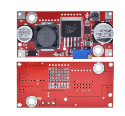
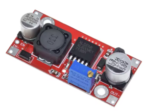
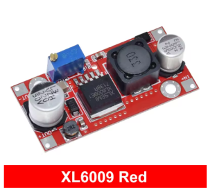
The XL6009 15W Adjustable Step-Up DC-DC Converter Module is a high-performance, compact boost converter designed to efficiently elevate lower DC voltages to higher, adjustable output levels. Featuring a built-in Enable Pin for remote on/off control, this module is ideal for applications where power management and sequencing are critical.
At the heart of this module is the XL6009E1 chip, a second-generation high-frequency switching regulator from XLSEMI that integrates a high-current 4A MOSFET switch . This advanced design delivers superior performance compared to older LM2577-based modules, with higher efficiency, higher switching frequency, and more compact overall dimensions .
Power Ratings:
Enable Pin Feature: The module includes an Enable (EN) control pin that allows you to remotely turn the converter on or off without disconnecting the input power. This is particularly useful for:
-
Power sequencing in multi-voltage systems
-
Reducing standby power consumption in battery-powered applications
-
Remote shutdown capability for safety systems
-
Microcontroller-controlled power management
Enable Pin Operation:
-
EN = HIGH (1.4V – VIN): Module ON (normal operation)
-
EN = LOW (0V – 0.8V): Module OFF (shutdown mode)
-
Floating (disconnected): Module ON by default
Superior to LM2577 – The Key Differences:
The XL6009’s 400kHz switching frequency is a dramatic upgrade over the LM2577’s 52kHz. This higher frequency allows for the use of smaller, lower-cost filter capacitors while achieving lower output ripple and a more compact module design . The higher efficiency (up to 94%) means less power is wasted as heat, improving reliability in compact designs.
Wide Operating Range:
-
Input Voltage: 3V – 32V (Optimal 5V – 32V)
-
Output Voltage: 5V – 50V (adjustable via onboard potentiometer)
-
Maximum Output Current: 2.5A (derate based on input/output conditions)
-
Maximum Input Current: 4A
-
Operating Temperature: -40°C to +85°C
Key Applications:
-
Automotive Voltage Regulation: Stabilizes vehicle electrical systems where voltage can fluctuate
-
Battery-Powered Devices: Converts single-cell Li-Ion batteries (3.7V) to 5V, 9V, or 12V
-
LED Lighting: Drives 12V or 24V LED strips from 5V USB power banks
-
Industrial Equipment: Provides higher voltage rails for sensors and actuators
-
Remote Power Control: Enable pin allows microcontroller-based power management
Important Operating Note: This module is a step-up (boost) converter only. The output voltage must be set higher than the input voltage for proper regulation. If the input exceeds the set output, the module cannot step down, and the output will approximately follow the input, potentially damaging your load.
Whether you are an electronics hobbyist, an IoT developer, or an industrial engineer, the XL6009 Step-Up Converter Module with Enable Pin provides a powerful, efficient, and user-friendly solution for all your voltage boosting needs.
Key Features
-
Enable Pin Control – Remote on/off capability for power management and sequencing; default ON when floating
-
Wide Input Voltage Range – Accepts DC 3V to 32V input (optimal 5V-32V), compatible with USB (5V), Li-Ion batteries, and car systems
-
Wide Adjustable Output – Output can be set from 5V up to 50V via onboard multi-turn potentiometer
-
4A Peak Input Current – Integrated 4A MOSFET switch delivers high power conversion capability
-
2.5A Maximum Output Current – Sufficient for a wide range of applications including LED lighting and sensor power
-
15W/25W Power Rating – 15W continuous without heatsink, 25W continuous with heatsink
-
High Conversion Efficiency – Up to 94% efficiency minimizes power loss and heat generation
-
400kHz High Switching Frequency – Enables smaller filter capacitors, lower output ripple (<50mV), and compact design
-
Screw Terminal Connections – Easy, solderless wiring for input and output connections
-
Wide Operating Temperature – -40°C to +85°C for reliable operation in automotive, industrial, and outdoor environments
Technical Parameters
Usage Guide
Pinout and Connection Description
The module features screw terminal blocks and pin headers for easy connections:
Note: Input and output grounds are common (connected together on the board).
Enable Pin Usage
The Enable (EN) pin provides remote control capability for the module:
Connecting the Enable Pin:
-
To a microcontroller: Connect EN directly to a GPIO pin (3.3V or 5V logic compatible)
-
To a mechanical switch: Connect EN to VIN+ through a switch (pull-up)
-
Leaving EN disconnected: Module remains ON (default behavior)
Enable Pin Current: The EN pin draws very little current (typically <10µA), making it suitable for direct connection to microcontroller GPIO pins without a buffer .
Wiring Instructions
Step 1 – Connect Input Power
Step 2 – Connect Load
Step 3 – (Optional) Connect Enable Pin for Remote Control
-
For always-on operation, leave EN pin disconnected (floating)
-
For remote control, connect EN to your control signal (microcontroller GPIO or switch)
Step 4 – Power On and Adjust
Adjusting the Output Voltage
⚠️ CRITICAL: The “Endless Turn” Issue
This is the most common point of confusion. The potentiometer often ships at its maximum resistance position. If you turn the screw and see no voltage change, you need to turn it counter-clockwise for 10-15 full rotations before the voltage begins to increase. Keep turning while watching your multimeter until the voltage starts to rise. The potentiometer is multi-turn, so you won’t damage it.
Proper Adjustment Procedure:
-
Power the module using your input source (5V-32V DC)
-
Set EN pin HIGH or leave floating (default ON)
-
Connect a multimeter to the OUT+ and OUT- terminals
-
Use a small screwdriver to turn the blue potentiometer:
-
Monitor the multimeter while adjusting
-
Adjust before connecting load – It is recommended to set output voltage with no load connected
Typical Voltage Settings by Application:
Power Ratings and Thermal Management
The module’s power rating depends on cooling:
Power Calculation Examples (15W limit without heatsink):
Real-World Power Test Results :
Important Current Relationship: Boost converters draw more input current than output current due to power conservation:
Power In × Efficiency = Power Out or VIN × IIN × Efficiency = VOUT × IOUT
Example: To get 1A at 12V output (12W) from a 5V input, the input current must be approximately 2.5A-3A (accounting for efficiency losses). Ensure your input power source can supply sufficient current.
Heat Management Tips:
-
Add a heatsink to the XL6009 chip for continuous loads above 1.5A or power above 15W
-
Ensure adequate airflow around the module
-
Consider using a higher input voltage to reduce the voltage conversion ratio and associated heat
-
The XL6009 lacks built-in thermal shutdown, so proper thermal design is essential
Important Operating Restrictions
Voltage Limitation (Critical):
This module is a step-up (boost) converter only. It CANNOT step down voltage. The output voltage must always be set higher than the input voltage for proper regulation. If the input voltage exceeds the set output voltage, the module will not regulate down, and the output will approximately follow the input voltage (minus a small diode drop), potentially delivering high voltage to your low-voltage load and destroying it.
Reverse Polarity Warning:
This module does NOT have reverse polarity protection . Double-check your IN+ and IN- connections before applying power. Connecting backwards will instantly destroy the module.
Short Circuit Protection:
Most XL6009 modules do not include dedicated short circuit protection . The chip has over-current limiting, but this is not a full protection feature. Adding a small fuse on the input line is good safety practice.
Using the Enable Pin with a Microcontroller (Arduino Example)
const int ENABLE_PIN = 7;
void setup() {
pinMode(ENABLE_PIN, OUTPUT);
digitalWrite(ENABLE_PIN, LOW);
delay(1000);
digitalWrite(ENABLE_PIN, HIGH);
Serial.begin(9600);
Serial.println("XL6009 Boost Converter Enabled");
}
void loop() {
digitalWrite(ENABLE_PIN, HIGH);
delay(10000);
digitalWrite(ENABLE_PIN, LOW);
delay(10000);
}
Enable Pin Voltage Compatibility:
-
3.3V logic (ESP32, Raspberry Pi, 3.3V Arduino): EN = 3.3V (HIGH) works correctly
-
5V logic (Arduino Uno/Mega): EN = 5V (HIGH) works correctly
-
The EN pin threshold is 1.4V for HIGH, so both 3.3V and 5V logic are compatible
Example Applications
Installation Tips
-
Polarity Check: Always double-check input polarity before applying power
-
Initial Setup: Adjust output voltage with no load connected first
-
Enable Pin: Leave floating for always-on operation; connect to control signal for remote management
-
Keep Wires Short: Long wires add resistance and inductance, reducing efficiency
-
Use a Fuse: Add a fuse (e.g., 3A-5A) on the input line as safety protection
-
Heat Sinking: For loads >15W or continuous high-power operation, attach a heatsink to the XL6009 chip
-
Start with Low Load: When first testing, use a low-current load to verify voltage setting before connecting sensitive equipment
-
Heatsink Installation: The XL6009 chip has a metal tab for heatsink attachment; use thermal adhesive or a clip-on heatsink
Q: Why is my output voltage not changing when I turn the potentiometer screw?
This is the most common issue. The potentiometer typically needs to be turned counter-clockwise for 10-15 full rotations before the voltage begins to change. Keep turning while watching your multimeter until the voltage starts to rise. The potentiometer is multi-turn, so you won’t damage it by continuing to turn
Q: How do I use the Enable pin?
The Enable (EN) pin provides remote on/off control :
-
Leave floating (disconnected): Module ON (default)
-
Connect to HIGH (1.4V – VIN): Module ON
-
Connect to LOW (0V – 0.8V): Module OFF
You can connect the EN pin directly to a microcontroller GPIO pin (3.3V or 5V compatible) or to a mechanical switch.
Q: What is the maximum power this module can handle?
Exceeding these limits will cause the module to overheat and may lead to permanent damage . The XL6009 chip lacks built-in thermal shutdown, so thermal management is critical
Q: What is the difference between this module and the LM2577?
The XL6009 is a superior modern alternative :
Q: Can I use this module to step down voltage (e.g., 12V to 5V)?
No. This module is a boost (step-up) converter only. It cannot step down voltage. If your input is 12V and you need 5V output, you need a buck converter module. If you need both step-up and step-down, use a SEPIC or buck-boost converter.
Q: Does this module have short circuit or reverse polarity protection?
No. Most XL6009 modules do not include these protections :
Always double-check polarity before powering on, and consider adding a fuse on the input.
Q: Why is my input current so high when boosting?
This is normal physics of boost conversion. Power is conserved: Power In × Efficiency = Power Out. When boosting voltage, input current increases proportionally. Example: 1A at 12V output (12W) from 5V input requires approximately 2.5A-3A input current.
Q: Can I use this module in a car (12V-14.5V electrical system)?
Yes. The XL6009 accepts 3V-32V input, making it perfect for automotive use. It can stabilize output voltage regardless of input fluctuations. However, ensure your load doesn’t exceed current limits and consider adding input protection against voltage spikes.
Q: Can I use this module for both home and business applications?
Home users: Powering 12V LED strips from USB power banks, boosting 3.7V batteries to 5V for Arduino projects, creating custom power supplies, running 12V fans from 5V USB.
Business users: Industrial equipment power supplies, automotive voltage stabilization, solar/wind power conditioning, LED lighting systems, prototype development, remote sensor networks.
Q: Why is my module getting very hot?
Heat is normal in boost converters, especially when :
-
Drawing high current (>1.5A continuous)
-
Boosting a low voltage to a much higher voltage
-
Operating without adequate airflow
-
Power exceeds 15W without heatsink
Solutions: Add a heatsink, reduce load current, use a higher input voltage (to reduce conversion ratio), or improve ventilation.