Product Overview
The LM2596/LM2576 DC-DC Buck Converter Module is a high-efficiency step-down switching regulator designed to convert higher DC voltages (such as 12V, 24V, or 36V) into a stable lower voltage, most commonly 5V . Based on the industry-standard LM2596 or LM2576 chipset from Texas Instruments (formerly National Semiconductor), this module provides a simple, reliable, and efficient solution for powering 5V devices from automotive batteries, industrial power rails, or solar-charged battery banks .
Unlike traditional linear voltage regulators that dissipate excess energy as heat, this switching regulator utilizes Pulse Width Modulation (PWM) technology to achieve conversion efficiencies of up to 90% or higher . This means it runs much cooler and wastes significantly less power, making it ideal for battery-powered or enclosed applications. The module is capable of delivering up to 3A of continuous output current, enough to power an Arduino, Raspberry Pi, a high-power LED strip, or simultaneously charge two smartphones .
This product is often available in two common configurations: a fixed 5V output version (ideal for USB charging and 5V logic systems) and an adjustable version (allowing you to set any output voltage between 1.25V and 35V via a precision potentiometer) . Many modules also feature a dual USB output option, making them perfect for custom car chargers or portable power stations .
Key Features
-
High-Efficiency Step-Down Conversion: Utilizes LM2596 (150kHz) or LM2576 (52kHz) switching regulator ICs to achieve efficiency up to 92%, minimizing power loss and heat generation compared to linear regulators .
-
Wide Input Voltage Range: Accepts DC input from 4.5V up to 40V, making it compatible with common 5V USB, 12V automotive, 24V industrial, and even 36V solar panel systems .
-
3A High Output Current: Capable of delivering up to 3A of continuous output current. For loads above 2.5A, a heatsink is recommended to maintain optimal performance .
-
Fixed 5V or Adjustable Output: Choose between a fixed 5V version (ideal for USB devices) or an adjustable version (1.25V–35V) with an onboard precision potentiometer for fine-tuning .
-
Integrated USB Output Options: Many models feature a dual USB-A output port with smart identification chips for charging Android and iOS devices simultaneously .
-
Comprehensive Protection: Includes over-current protection (OCP), thermal shutdown, and short-circuit protection to safeguard the module and your connected devices .
-
Low Output Ripple: Delivers clean power with output ripple typically less than 30mV, suitable for sensitive electronics like microcontrollers and audio equipment .
-
Compact and Lightweight: Small PCB footprint (approx. 43mm × 21mm) with screw terminals or USB ports for easy integration into various projects .
-
Industrial Temperature Range: Designed to operate reliably from -40°C to +85°C, suitable for harsh environments .
Technical Specifications
Pinout & Interface Guide
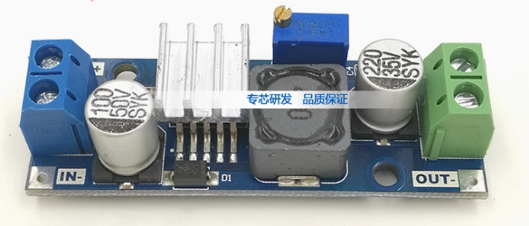
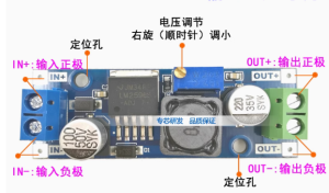
The module is clearly labeled for easy wiring. Connection points vary slightly between models but generally include:
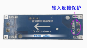
Input Side (Power Source)
-
IN+ (VIN): Connect to the positive terminal of your DC power source (e.g., 12V battery, 24V power supply).
-
IN- (GND): Connect to the negative terminal (ground) of your DC power source.
Output Side (Load Connection)
-
OUT+ (VOUT): Connect to the positive terminal of your 5V device (e.g., Arduino 5V pin, Raspberry Pi 5V pin).
-
OUT- (GND): Connect to the negative terminal (ground) of your device.
USB Output (for Dual USB Models)
Adjustable Potentiometer (for Adjustable Models)
-
Precision Potentiometer: A small multi-turn potentiometer (blue box) is used to finely adjust the output voltage. Important: On most models, turning the potentiometer counter-clockwise increases the output voltage, and clockwise decreases it. Always adjust with a multimeter connected to the output .
Status LED
Usage Guide
Wiring Instructions
IMPORTANT: Always disconnect the input power source before wiring or modifying connections.
Basic Connection for Fixed 5V Output
-
Connect Input: Connect the positive wire of your DC power source (e.g., 12V battery) to the IN+ terminal. Connect the negative wire to the IN- terminal.
-
Connect Load: Connect the positive wire of your 5V device to the OUT+ terminal. Connect the negative wire to the OUT- terminal.
-
Power On: Apply power to the input. The status LED will light up, and your 5V device will be powered.
Adjusting Output Voltage (For Adjustable Version)
Caution: Do not short-circuit the output terminals while adjusting, as this may damage the potentiometer or the module.
-
Power the Module: Connect a suitable DC power source (e.g., 12V) to the input terminals.
-
Connect Multimeter: Set your multimeter to measure DC voltage (20V range). Connect the probes to the OUT+ (positive) and OUT- (negative) terminals.
-
Adjust Potentiometer: Using a small flathead screwdriver, turn the blue potentiometer on the module.
-
To increase the output voltage, turn the potentiometer counter-clockwise.
-
To decrease the output voltage, turn the potentiometer clockwise.
-
Set Desired Voltage: Slowly adjust until your multimeter reads the desired voltage (e.g., 5.0V, 12.0V, 24.0V). Note: The input voltage must be at least 1.5V higher than the desired output voltage for stable regulation .
Powering a Raspberry Pi from a Car Battery
A classic and highly effective application for this module is powering a Raspberry Pi or other 5V single-board computer from a 12V vehicle battery.
-
Connect the module’s IN+ and IN- terminals to the 12V car battery (or a 12V power supply).
-
Connect a USB cable to the module’s USB-A port (or connect directly to the OUT+ and OUT- terminals).
-
Plug the other end of the USB cable into the Raspberry Pi’s power input (USB-C or Micro-USB). The module’s 5V 3A output is perfectly suited to power the Pi.
-
Pro-Tip: The module’s high efficiency means you won’t drain your car battery as quickly as using a linear regulator, and you can leave it connected without significant parasitic draw.
Powering an Arduino from a 24V Industrial Supply
In an industrial automation setting, 24V DC is a common standard. This module can step that down to 5V to power an Arduino Pro Mini or an ESP8266.
-
Connect the 24V power supply’s positive rail to IN+ and the negative rail to IN-.
-
Connect the Arduino’s 5V pin to OUT+ and the Arduino’s GND to OUT-.
-
The module will efficiently provide clean 5V power to your microcontroller, even in a noisy industrial environment, thanks to its built-in filtering capacitors and 150kHz switching frequency .
Output Capacity vs. Input Voltage and Heat Management
The module’s maximum output current is rated at 3A, but this is under ideal conditions. The actual achievable current is influenced by the input voltage, the input-output voltage differential, and ambient temperature.
Heat Management: For loads above 2A or when the input voltage is significantly higher than the output (e.g., 24V to 5V), the LM2596/LM2576 chip will generate noticeable heat. It is highly recommended to attach a small heatsink (e.g., 10mm × 10mm) to the metal tab of the IC using thermal adhesive tape to ensure long-term reliability and prevent thermal shutdown .
Q: What is the difference between LM2596 and LM2576? Which one is better?
Both are excellent step-down switching regulators from Texas Instruments. The key differences lie in their switching frequency .
-
LM2596: Operates at a higher frequency of 150kHz. This allows for the use of smaller and less expensive external components (inductors and capacitors), making the overall module more compact. It also generally has lower output ripple and higher efficiency, especially at lower loads
-
LM2576: Operates at a lower frequency of 52kHz. It is a more traditional, robust design that is very popular in industrial applications. It requires larger external components but is known for its ruggedness and reliability .
-
For most hobbyist and modern applications, the LM2596 is the preferred choice due to its smaller size, higher efficiency, and lower output noise.
Q: Can this module increase voltage (boost)?
No. This is a buck (step-down) converter only. The output voltage must always be lower than the input voltage. The input must be at least 1.5V higher than the desired output for the regulator to function correctly . To increase voltage, you would need a separate boost converter.
Q: Can I use this module to charge a 12V lead-acid battery from a 24V source?
Yes, but with caution. You would use the adjustable version of this module. You would set the output voltage to the battery’s float charge voltage (e.g., 13.8V for a 12V lead-acid battery) and set a current limit. However, a standard buck converter module lacks a dedicated constant current (CC) charging profile, so it is not ideal for unattended charging. It’s better to use a dedicated battery charger.
Q: What is the difference between the fixed 5V version and the adjustable version?
The fixed 5V version has its output voltage internally set to 5V. It has no potentiometer and is a simple “plug-and-play” solution for powering 5V USB devices. The adjustable version has a potentiometer that allows you to set the output to any voltage between 1.25V and 35V, offering much greater flexibility for various projects
Q: The module gets very hot. Is this normal?
While some heat is normal, especially under high load or with a large input-output voltage differential, the module should not be too hot to touch. If it is extremely hot:
-
Add a Heatsink: The most common solution is to attach a small aluminum heatsink to the LM2596/LM2576 IC .
-
Reduce Load: Ensure your load is not drawing more than 3A.
-
Improve Airflow: Ensure the module is in a well-ventilated area.
-
Lower Input Voltage: If you are converting from 36V to 5V, consider using two modules in series (36V to 12V, then 12V to 5V) to spread the heat dissipation.
Q: My output voltage is fluctuating or inaccurate.
This is often a calibration issue with the adjustable version. Connect a multimeter to the output and carefully adjust the onboard potentiometer. Also, ensure your input voltage is stable and at least 1.5V higher than the output.
Q: What is the maximum output current I can draw from the USB ports?
On dual USB models, the total output current across both ports is typically 3A (max). This means you could charge two smartphones simultaneously, drawing about 1.5A each. The USB port’s smart identification chip will help negotiate the optimal charging current with your device .
Q: Can I use this module to power a motor or other inductive load directly?
While possible, motors are inductive loads that can generate voltage spikes (back-EMF) that may damage the regulator. It is highly recommended to add a flyback diode across the motor terminals to protect the module.
Q: The module has power (LED is on) but there is no output voltage.
Follow this checklist:
-
Check the ON/OFF Enable Pin: Some modules have a separate “EN” or “ON/OFF” pin. If present, it must be connected to the input voltage (VIN) to enable the output. If left floating, the module may be in shutdown mode.
-
Check Output Wiring: Ensure there is no short circuit on the output terminals.
-
Check Potentiometer: If it’s an adjustable model, the potentiometer may be turned fully counter-clockwise (minimum voltage). Try adjusting it clockwise while monitoring the output with a multimeter.
-
Check Input Voltage: Ensure your input voltage is at least 1.5V higher than your desired output voltage .
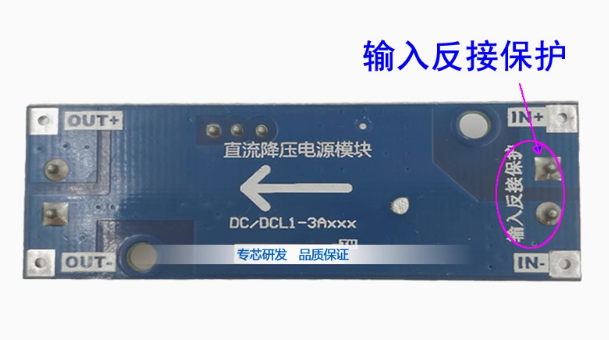
Q: Can I connect the input and output in reverse?
No. Reversing the input polarity (connecting IN+ to negative and IN- to positive) will instantly destroy the module. Always double-check your wiring before applying power . Reversing the output polarity will not damage the module but may damage your connected device.
Q: Is this module suitable for powering sensitive audio equipment?
While the LM2596 has low ripple (≤30mV), for extremely sensitive audio or measurement equipment, you may want to add an additional LC filter (a small inductor and capacitor) to the output to further reduce high-frequency switching noise.