Product Overview
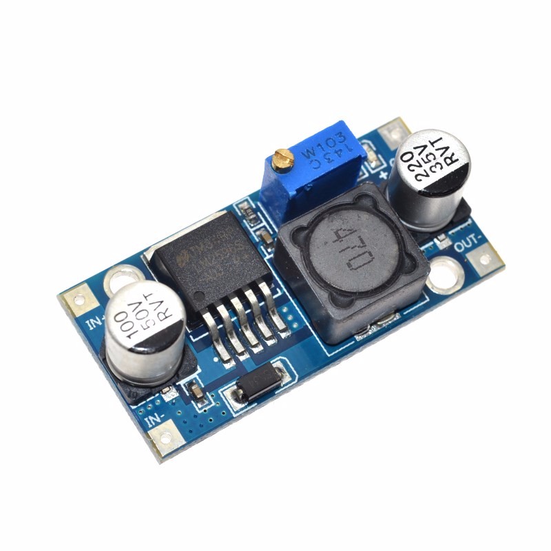
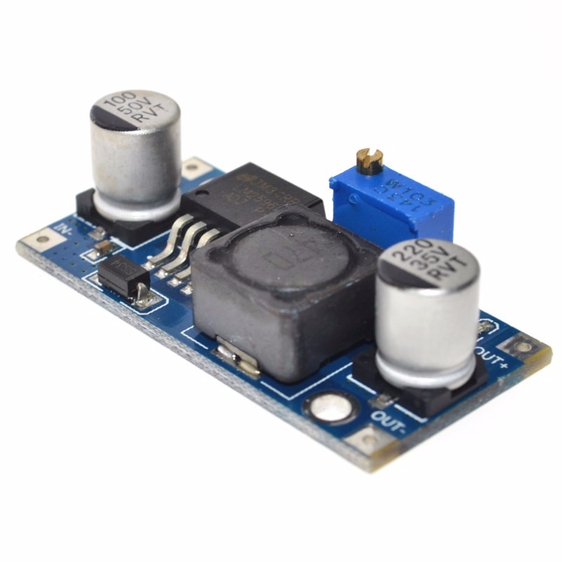
The LM2596 3A Adjustable Buck Converter Module is a high-performance, step-down switching regulator based on the industry-standard LM2596 chip from Texas Instruments . This module efficiently converts higher DC voltages (such as 24V, 12V, or 36V) into a lower, stable, and continuously adjustable output voltage, making it an essential tool for powering a wide variety of electronic devices .
Unlike traditional linear voltage regulators that dissipate excess energy as heat, this switching regulator uses Pulse Width Modulation (PWM) technology to achieve conversion efficiencies of up to 92% . This means it runs much cooler and wastes significantly less power, making it ideal for battery-powered or enclosed applications. The module is capable of delivering up to 3A of continuous output current, enough to power an Arduino, Raspberry Pi, a high-power LED strip, or other 5V/12V logic systems .
The module features a simple three-terminal interface and an onboard precision potentiometer for adjusting the output voltage. This makes it a favorite among electronics hobbyists, educators, and professionals for creating custom power supplies, retrofitting old electronics, and developing IoT devices .
Key Features
-
High-Efficiency Step-Down Conversion: Utilizes the LM2596 switching regulator to achieve up to 92% efficiency, minimizing power loss and heat generation compared to linear regulators .
-
Wide Input Voltage Range: Accepts DC input from 4.5V to 40V, making it compatible with common 5V USB, 12V automotive, 24V industrial, and even 36V solar panel systems .
-
Adjustable Output Voltage: Provides a continuously adjustable output from 1.25V to 35V via an onboard precision potentiometer, allowing you to set exactly the voltage your project needs .
-
3A High Output Current: Capable of delivering up to 3A of output current. For loads above 2.5A, a heatsink is recommended to maintain optimal performance .
-
High Switching Frequency: Operates at a fixed 150kHz internal oscillator, allowing for smaller-sized filter components and lower output ripple compared to older regulator designs .
-
Comprehensive Protection: Includes built-in thermal shutdown and current-limit protection to safeguard the module and your connected devices under fault conditions .
-
Low Output Ripple: Delivers clean power with output ripple typically less than 30mV, suitable for sensitive electronics like microcontrollers and audio equipment .
-
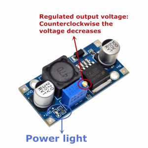
LED Indicator: An onboard LED provides clear visual confirmation when the input power is applied and the module is operational .
-
Industrial Temperature Range: Designed to operate reliably from -45°C to +85°C, suitable for a variety of environments .
Technical Specifications
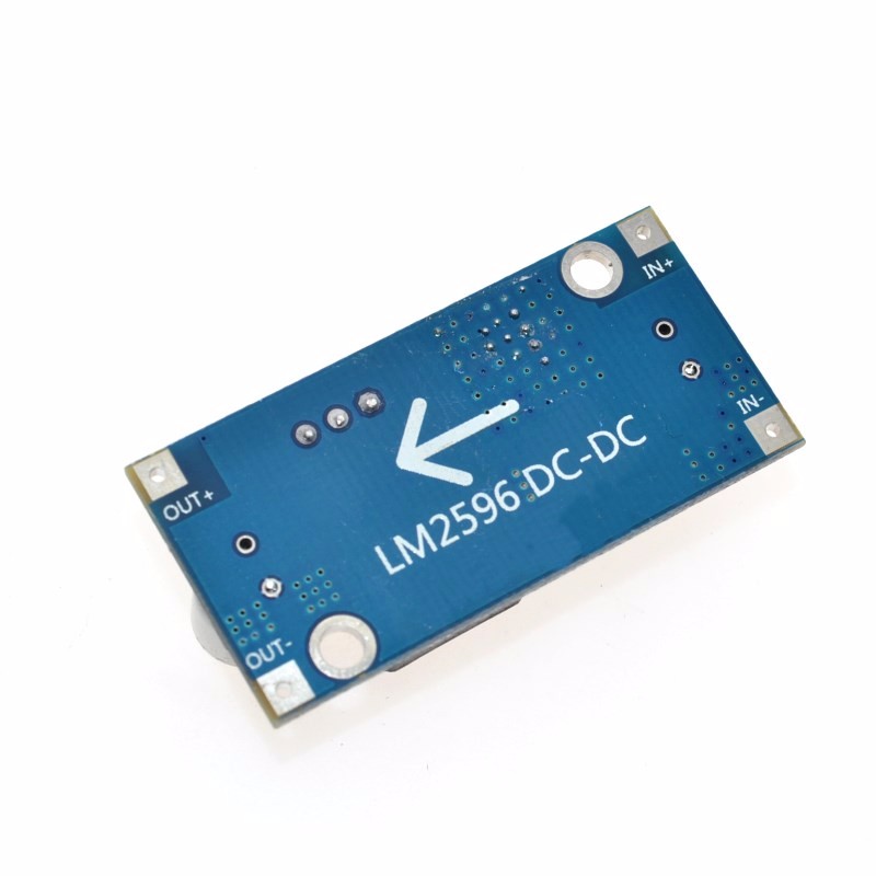
Pinout & Interface Guide
The module is clearly labeled for easy wiring. Connection points include:
Input Side (Power Source)
-
IN+ (VIN): Connect to the positive terminal of your DC power source (e.g., 12V battery, 24V power supply).
-
IN- (GND): Connect to the negative terminal (ground) of your DC power source.
Output Side (Load Connection)
-
OUT+ (VOUT): Connect to the positive terminal of your 5V/12V device (e.g., Arduino 5V pin, LED anode).
-
OUT- (GND): Connect to the negative terminal (ground) of your device.
User Controls
Status Indicators
Usage Guide
Wiring Instructions
IMPORTANT: Always disconnect the input power source before wiring or modifying connections.
-
Connect Input: Connect the positive wire of your DC power source (e.g., 12V battery) to the IN+ terminal. Connect the negative wire to the IN- terminal .
-
Set Initial Voltage: Before connecting your load, turn the blue potentiometer clockwise a number of turns (15+) to increase the output voltage, or counter-clockwise to decrease it . The factory default is often set to a high voltage (around 18V) .
-
Power On & Adjust Voltage: Apply power. Use a multimeter on the output terminals. Slowly adjust the potentiometer until you reach your desired output voltage (e.g., 5.0V for a Raspberry Pi, 12V for a fan) .
-
Connect Load: Turn off power, connect your device to OUT+ and OUT-, and re-apply power.
Example: Powering a 5V Device from a 24V Source
This is a classic and highly effective application for the LM2596 module .
-
Connect the 24V power supply’s positive rail to IN+ and the negative rail to IN-.
-
Connect a multimeter to the OUT+ and OUT- terminals.
-
Apply power and carefully adjust the potentiometer until the multimeter reads exactly 5.00V.
-
Turn off the power, connect your 5V device (e.g., Arduino, ESP8266, Raspberry Pi) to the output terminals, and turn the power back on. The module will efficiently provide clean 5V power to your device.
Important Considerations
-
Step-Down Only: This is a buck (step-down) converter only. The output voltage must always be lower than the input voltage. The input must be at least 1.5V higher than the desired output for stable regulation .
-
Heat Management: For loads above 2A, it is recommended to attach a small heatsink to the metal tab of the LM2596 IC to ensure long-term reliability and prevent thermal shutdown .
-
Potentiometer Adjustment: The potentiometer has a wide adjustment range. It may require 10-15 turns before you see a significant change in the output voltage .
-
Input Capacitor: For stable operation, especially when using long input wires, it is good practice to have a 100µF electrolytic capacitor near the input terminals.
Q: What is the difference between a buck converter and a boost converter?
A buck converter (step-down) decreases a higher input voltage to a lower output voltage (e.g., 24V to 5V). A boost converter (step-up) increases a lower input voltage to a higher output voltage. This module is a buck converter only
Q: Can this module increase voltage (boost)?
No. This is a buck (step-down) converter only. The output voltage must always be lower than the input voltage. The input must be at least 1.5V higher than the desired output for the regulator to function correctly
Q: What is the maximum output current I can draw from this module?
The module is rated for a maximum of 3A. For long-term reliability, it is recommended to stay within 2A – 2.5A, and a heatsink should be used for loads above 2A
Q: Can I use this module to power a Raspberry Pi or Arduino?
Yes. This module is excellent for powering 5V logic systems. By adjusting the output to 5.0V, you can power an Arduino, ESP8266, or Raspberry Pi from a higher voltage source like a 12V battery
Q: Why is my output voltage not changing when I turn the potentiometer?
The potentiometer has a wide adjustment range. You may need to turn it 10-15 full rotations before you see a change in the output voltage. Keep turning it clockwise to increase the voltage
Q: The module gets hot. Is this normal?
Some heat is normal, especially under high load. If it is too hot to touch, attach a heatsink to the LM2596 IC. Also, ensure the input voltage is not excessively higher than the output, as a larger voltage differential generates more heat
Q: What is the input voltage range for this module?
The input voltage range is 4.5V to 40V DC. However, for a stable regulated output, the input voltage must be at least 1.5V higher than your desired output voltage
Q: How accurate is the output voltage?
The LM2596 has excellent line and load regulation. As a practical guide, users have reported that the voltage remains stable under load, with one user noting that a 5.00V output for their Raspberry Pi remained constant even when the Pi was drawing its normal operating current
Q: The module has power (LED is on) but there is no output voltage.
Follow this checklist:
-
Check the potentiometer setting. It may be turned fully counter-clockwise (minimum voltage). Try turning it clockwise 10-15 turns while monitoring the output with a multimeter.
-
Check that there is no short circuit on the output terminals.
-
Verify that your input voltage is at least 1.5V higher than your target output voltage
Q: Can I connect the input and output in reverse?
No. Reversing the input polarity (connecting IN+ to negative and IN- to positive) will instantly destroy the module. Always double-check your wiring before applying power
Q: Can I use this module to charge a battery?
While the module can be used to charge batteries (e.g., setting output to 12.6V for a 3S Li-ion battery), it lacks a dedicated constant current (CC) charging profile. For unattended charging, it is safer to use a dedicated battery charger module