Product Overview
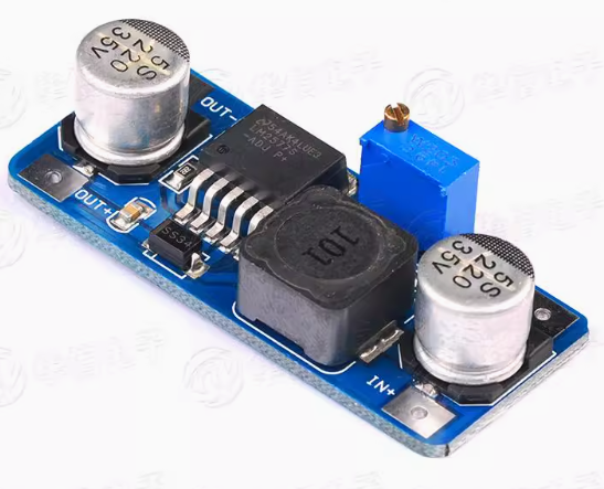
The LM2577 DC-DC Step-Up Power Converter Module is a high-performance boost switching regulator designed to convert lower DC voltages into higher, adjustable output voltages. Based on the industry-standard LM2577 chip from Texas Instruments, this module efficiently steps up voltages from sources such as 3.7V Li-ion batteries, 5V USB, or 12V car batteries to higher levels like 12V, 24V, or even 48V .
Unlike linear regulators that waste excess voltage as heat, this switching regulator uses Pulse Width Modulation (PWM) technology at a fixed 52kHz switching frequency to achieve conversion efficiencies of up to 80% . This makes it ideal for battery-powered applications where power conservation is critical. The module can deliver up to 3A of output current and supports a wide input voltage range from 3.5V to 40V .
The LM2577 is highly versatile, supporting boost, flyback, and forward converter topologies . It includes built-in protection features such as current limiting, undervoltage lockout, thermal shutdown, and a soft-start function to reduce inrush current during startup . This module is the perfect choice for powering devices that require higher voltage than your available power source can provide—whether you’re building a portable power supply, charging lithium battery packs, or driving high-voltage LED arrays.
Key Features
-
Adjustable Output Voltage: Provides continuously adjustable output from 1.23V to 60V via onboard potentiometer, allowing you to set exactly the voltage your project needs
-
High-Efficiency Step-Up Conversion: Utilizes the LM2577 switching regulator with 52kHz fixed-frequency oscillator to achieve up to 80% efficiency, minimizing power loss and heat generation
-
Wide Input Voltage Range: Accepts DC input from 3.5V to 40V, compatible with single-cell Li-ion (3.7V), USB (5V), car batteries (12V), and industrial power sources
-
3A High Output Current: Capable of delivering up to 3A of output current (peak). For loads above 2A, a heatsink is recommended
-
Multiple Topology Support: Can be configured as a boost (step-up), flyback, or forward converter for maximum design flexibility
-
Built-in Protection Features: Includes output switch current limiting, undervoltage lockout, and thermal shutdown to safeguard the module and your connected devices
-
Soft-Start Function: Reduces inrush current during startup, protecting both the module and the power source
-
Wide Operating Temperature: Rated for operation from -40°C to +125°C, suitable for demanding industrial and automotive environments
-
Requires Few External Components: Simple design with minimal external components, making the module compact and reliable
Technical Specifications
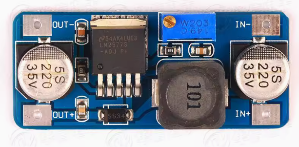
Pinout & Interface Guide
Input Side (Power Source)
-
IN+ (VIN): Connect to the positive terminal of your DC power source (e.g., 3.7V battery, 5V USB, 12V car adapter)
-
IN- (GND): Connect to the negative terminal (ground) of your DC power source
Output Side (Load Connection)
-
OUT+ (VOUT): Connect to the positive terminal of your device (e.g., 12V LED strip, 24V motor, battery to charge)
-
OUT- (GND): Connect to the negative terminal (ground) of your device
User Controls
Status Indicators
Usage Guide
Wiring Instructions
IMPORTANT: Always disconnect the input power source before wiring or modifying connections. Double-check polarity before applying power.
-
Connect Input: Connect the positive wire of your DC power source to the IN+ terminal. Connect the negative wire to the IN- terminal.
-
Set Initial Voltage: Before connecting your load, turn the blue potentiometer fully counter-clockwise to set the output voltage to its minimum (1.23V).
-
Power On & Adjust Voltage: Apply power. Use a multimeter on the output terminals. Slowly turn the potentiometer clockwise until you reach your desired output voltage (e.g., 12.0V for LED lighting, 16.8V for 4S Li-ion charging).
-
Connect Load: Turn off power, connect your device to OUT+ and OUT-, and re-apply power.
Example 1: 3.7V Li-ion Battery to 5V USB Output
Power a USB device from a single 18650 lithium battery.
-
Connect the 3.7V battery’s positive terminal to IN+ and negative to IN-
-
Connect a multimeter to OUT+ and OUT- terminals
-
Apply power and carefully adjust the potentiometer until the multimeter reads exactly 5.0V
-
Connect your USB device (phone charger, LED light) to the output terminals
Important: The output voltage must be higher than the input voltage for boost operation. A 3.7V input can be boosted to 5V, 9V, 12V, etc., but cannot be lowered below 3.7V.
Example 2: 12V Car Battery to 24V LED Lighting
Power 24V LED strips from a 12V vehicle electrical system.
-
Connect the 12V car battery’s positive terminal to IN+ and negative to IN-
-
Set the output voltage to 24.0V using the potentiometer and a multimeter
-
Connect your 24V LED strip to the output terminals
-
The module will efficiently step up 12V to 24V for your lighting
Example 3: Charging a 4S Li-ion Battery Pack
Charge a 4-cell Li-ion battery pack (maximum voltage 16.8V) from a 12V power supply.
-
Connect the 12V power supply to IN+ and IN-
-
Set the output voltage to 16.8V (4S Li-ion fully charged voltage)
-
Set the current limit if available (not all modules have CC adjustment)
-
Connect the battery pack to OUT+ and OUT- (ensure correct polarity)
Important Considerations
-
Step-Up Only: This is a boost (step-up) converter only. The output voltage must always be higher than the input voltage. For step-down applications, use a buck converter like the LM2596
-
Minimum Load: The LM2577 may require a minimum load for stable regulation. Very light loads may result in output voltage fluctuations
-
Heat Management: For loads above 2A, a heatsink is strongly recommended. At 3A continuous, the module will get hot—ensure adequate ventilation
-
Input Current: When boosting voltage, the input current is higher than the output current. For example, to get 12V 1A output from 5V input (80% efficiency), the input current will be approximately 3A. Ensure your power source can supply sufficient current
-
Potentiometer Adjustment: The potentiometer has a wide adjustment range. It may require multiple turns before you see a significant change in the output voltage
-
Feedback Resistors: For the adjustable version, the output voltage is set using external resistor dividers. The internal reference voltage is 1.23V
Q: What is the difference between a boost converter and a buck converter?
A boost converter (step-up) increases a lower input voltage to a higher output voltage (e.g., 5V to 12V). A buck converter (step-down) decreases a higher input voltage to a lower output voltage (e.g., 24V to 5V). This module is a boost converter only
Q: Can this module decrease voltage (buck)?
No. This is a boost (step-up) converter only. The output voltage must always be higher than the input voltage. If you apply 12V input and set the output to 5V, the output will follow the input (minus a diode drop) and cannot be regulated down .
Q: What is the maximum output current I can draw from this module?
The module is rated for a maximum of 3A peak. For long-term reliability, it is recommended to stay within 2A – 2.5A, and a heatsink should be used for loads above 2A .
Q: What is the minimum input voltage required?
The LM2577 requires a minimum input voltage of 3.5V to start and operate correctly . This makes it compatible with single 18650 Li-ion batteries (3.7V nominal).
Q: Why is my output voltage not changing when I turn the potentiometer?
The potentiometer may require multiple rotations. Try turning it 10-15 full rotations in each direction while monitoring the output with a multimeter. If still no change, check your wiring and input voltage.
Q: The module gets hot. Is this normal?
Some heat is normal, especially under high load (near 3A). If it is too hot to touch, you should:
-
Attach a heatsink to the LM2577 IC’s metal tab
-
Reduce the load current to below 2A
-
Ensure adequate airflow around the module
Q: What is the efficiency of this converter?
The LM2577 achieves up to 80% conversion efficiency under optimal conditions . This is significantly higher than linear regulators but lower than modern synchronous boost converters. The efficiency varies with input/output voltage differential and load current.
Q: What is the switching frequency?
The LM2577 operates at a fixed 52 kHz switching frequency . This allows for efficient power conversion while keeping external component sizes reasonable.
Q: Can I use this module to charge batteries?
Yes, with caution. The LM2577 can be used to charge batteries in constant voltage (CV) mode. However, for lithium batteries, you need a proper constant current/constant voltage (CC/CV) charging profile. If using this module, set the output to the battery’s float voltage and use an external current-limiting resistor or dedicated charger circuit.
Q: The module has power but there is no output voltage. What's wrong?
Follow this checklist:
-
Check that your input voltage is above 3.5V
-
Check the potentiometer setting—it may be turned fully counter-clockwise (minimum voltage)
-
Check that there is no short circuit on the output terminals
-
Verify that your load is not drawing more than 3A
-
Check if the module is in thermal shutdown (let it cool down and retry)
Q: Can I connect the input in reverse?
No. Reversing the input polarity may damage the module. Always double-check your wiring before applying power. Some modules may include reverse polarity protection, but not all variants do.
Q: Why is my output voltage equal to my input voltage?
This indicates the module is not boosting. Possible causes:
-
The potentiometer is not properly adjusted
-
The module is damaged (switch transistor failed short)
-
The load is drawing too much current
-
The input voltage is below the minimum required
Q: The output voltage fluctuates or is unstable.
This can be caused by:
-
An unstable or insufficient input power supply (voltage sag under load)
-
The load being too light (no minimum load condition)
-
Loose connections or insufficient wire gauge
-
The module overheating and entering thermal throttling
Q: What can I build with this boost converter module?
Popular applications include:
-
USB power banks: Boost 3.7V Li-ion battery to 5V for phone charging
-
LED lighting: Power 12V or 24V LED strips from 5V USB or 3.7V batteries
-
Battery charging: Charge higher voltage battery packs (e.g., charge 4S Li-ion from 12V)
-
Laptop car chargers: Boost 12V car battery to 19V for laptop power
-
DIY bench power supplies: Create variable voltage sources up to 60V
-
Solar power systems: Boost solar panel voltage to charge battery banks
Q: Can I use this module to power a 12V device from a 5V USB power bank?
Yes. Connect the 5V USB power bank to the input, set the output to 12V, and you can power 12V devices like LED strips, fans, or small pumps. Ensure the USB power bank can supply sufficient current (for 12V 1A output, expect ~2.5A input draw).
Q: Can I run two modules in parallel for more current?
Not recommended. Running switching regulators in parallel without proper current-sharing circuitry can cause one module to supply most of the load, leading to overheating and failure. For higher current, use a single higher-rated converter or design proper load-sharing circuits.
Q: What is the maximum output voltage I can achieve?
The LM2577 can produce up to 60V output . However, the maximum achievable output voltage depends on your input voltage, load current, and component selection. For very high output voltages, additional considerations for component ratings are necessary.