Product Overview
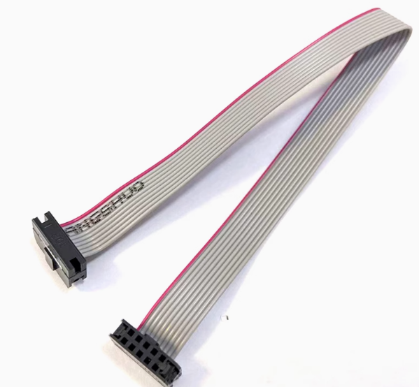
The ISP Download Cable with FC10P Connector is a high-quality 10-pin flat ribbon cable specifically designed for in-system programming (ISP) and JTAG debugging applications. This 20cm cable serves as the essential bridge between your ISP programmer (such as USBASP, STK500, or AVR programmer) and your target microcontroller board, enabling firmware uploads, debugging, and boundary-scan testing without removing the chip from its circuit.
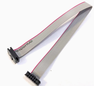
The cable features a standard 10-pin IDC (Insulation Displacement Connector) box header with a 2.54mm (0.1-inch) pin spacing, making it compatible with virtually all development boards, evaluation kits, and custom PCBs that adhere to the common ISP/JTAG pinout standard. The gray flat ribbon construction provides excellent flexibility and durability, while the 20cm length is optimized for desktop development—long enough for convenient workspace arrangement yet short enough to minimize signal degradation and electromagnetic interference.
Whether you are programming AVR microcontrollers (ATmega, ATtiny series), 51 series chips, ARM-based devices via JTAG, or simply prototyping with Arduino or other embedded platforms, this FC10P ISP cable is an indispensable tool for your electronics workbench. The connector features a polarized key (often with a missing pin or notch) to prevent incorrect orientation, ensuring safe and reliable connections every time.
Key Features
-
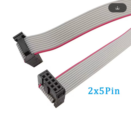
10-Pin FC10P IDC Connector: Standard 2×5 configuration with 2.54mm pitch for compatibility with common ISP/JTAG interfaces
-
Optimized 20cm Length: Goldilocks length for desktop development—long enough to reach comfortably, short enough to maintain signal integrity
-
Flat Ribbon Cable Construction: Organized, flexible 10-conductor wiring with easy identification and routing
-
2.54mm Pin Spacing: Matches standard breadboard, perfboard, and header pin layouts for universal compatibility
-
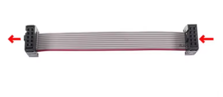
Polarized Connector Design: Prevents reverse insertion; ensures correct alignment when connecting to target boards
-
Durable Gray PVC Jacket: Flexible yet resilient insulation that resists kinking and wear during repeated use
-
28 AWG Conductor Size: Sufficient current capacity for programming signals with minimal voltage drop
-
Plug-and-Play Compatibility: Works with USBASP, STK500, AVRISP, and most ISP/JTAG programmers
Technical Specifications
Pinout & Interface Guide
The FC10P connector follows a standard 2×5 pin arrangement (2 rows of 5 pins). While specific pin assignments can vary slightly between programmers and target boards, the most common ISP pinout is:
Polarization Feature: The connector typically has a missing pin or a notch on one side to ensure correct orientation when connecting to the target board. Always align Pin 1 indicator (often marked with a triangle or dot on the programmer board) with Pin 1 on the cable connector.
Important: Before connecting to your target device, verify the specific pinout required by your programmer and target board. Some JTAG implementations may use a different pin mapping.
Usage Guide
Connecting to Your Setup
-
Identify Pin 1: Locate the Pin 1 indicator on your ISP programmer (often marked with a dot, triangle, or “1” printed on the PCB) and on the target board.
-
Align the Connector: Match the Pin 1 position on the cable connector to Pin 1 on both devices. The connector’s polarization key will help ensure correct orientation.
-
Seat the Connector: Gently press the IDC connector onto the header pins of your programmer and target board. The connector should slide on smoothly without excessive force. You should feel it snap into place.
-
Verify Connection: Ensure both ends are fully seated and secure before applying power or attempting to program.
Typical Applications
1. Programming AVR Microcontrollers with USBASP:
-
Connect USBASP programmer to your computer via USB
-
Connect this FC10P cable between USBASP and target AVR board
-
Open AVRDUDE, ProgISP, or Arduino IDE
-
Select appropriate chip and programmer settings
-
Upload firmware
2. Burning Bootloader to Arduino Board:
-
Connect FC10P cable from USBASP to Arduino ICSP header
-
In Arduino IDE: Tools → Programmer → USBasp
-
Select Tools → Burn Bootloader
3. JTAG Debugging:
-
For compatible ARM or other JTAG-enabled devices, connect the cable between debug probe and target
-
Use appropriate debugging software (OpenOCD, etc.)
Important Considerations
-
Power Before Programming: Ensure your target board is properly powered (either from the programmer’s VCC line or an external supply) before attempting to program.
-
Signal Integrity: The 20cm length is optimal for maintaining signal quality. For longer runs (50cm+), be aware of potential signal degradation and interference, especially at higher programming speeds.
-
Avoid Excessive Bending: While the flat cable is flexible, repeated sharp bending can damage internal conductors. Route cables with gentle curves.
-
Keep Away from Noise Sources: Programmer cables carry sensitive clock and data signals. Avoid routing near power supplies, motors, or other sources of electromagnetic interference.
-
Hot-Swap Caution: While some programmers support hot-swapping, it is generally safer to power down both programmer and target before connecting or disconnecting the cable.
Q: What is the difference between ISP and JTAG?
ISP (In-System Programming) and JTAG (Joint Test Action Group) are both protocols for programming and debugging microcontrollers, but they serve slightly different purposes. ISP is primarily for programming flash memory, while JTAG offers more advanced debugging features like boundary-scan testing. This cable works with both standards on compatible hardware, as the physical 10-pin connector is commonly used for ISP (AVR) and some JTAG implementations
Q: Why 20cm specifically? Why not longer or shorter?
The 20cm length is considered the “goldilocks” length for desktop development. Shorter cables (e.g., 10cm) can make workspace arrangement difficult as the programmer sits too close to the target board. Longer cables (e.g., 50cm+) can introduce signal attenuation, cross-talk, and increased susceptibility to electromagnetic interference, leading to communication errors, especially at higher programming speeds
Q: Will this cable work with my USBASP programmer?
Yes. USBASP programmers use the standard 10-pin ISP connector with 2.54mm pitch, making this FC10P cable a perfect match. The cable is widely described as the “golden partner” for USBASP in AVR programming applications
Q: What microcontrollers can I program with this cable?
This cable is compatible with:
-
AVR series: ATmega, ATtiny, AT90S, etc.
-
51 series: AT89S51, AT89S52, and similar ISP-capable 51 chips
-
ARM devices: Some ARM microcontrollers support JTAG over 10-pin interfaces
-
Arduino boards: When programming via the ICSP header
Q: How do I know which way to plug in the connector?
Look for the polarization key on the connector—typically a missing pin or a notch on the housing. Most ISP programmers and target boards have a Pin 1 indicator (a dot, triangle, or number “1” printed on the PCB). Align the cable’s Pin 1 (often marked with a colored wire or arrow) with the Pin 1 indicator on both devices
Q: The programmer reports "No target detected." What should I do?
Follow this checklist:
-
Check connections: Ensure both ends of the cable are fully seated on the header pins
-
Verify power: Your target board must be powered (either via programmer VCC or external supply)
-
Check orientation: Pin 1 may be mismatched—try flipping the connector at one end
-
Check programmer drivers: Ensure your computer recognizes the ISP programmer
-
Try a different cable: If available, test with another cable to rule out a faulty unit
Q: Can I use this cable to connect two development boards together?
This cable is designed to connect a programmer to a target board, not for direct board-to-board communication. It carries programming signals (MOSI, MISO, SCK, RST) which are not standard data communication lines for general-purpose use.
Q: Will this cable work with 3.3V logic systems?
Yes, but with caution. The cable itself is passive—it only carries signals. The voltage levels are determined by your programmer and target board. If your programmer outputs 5V signals and your target uses 3.3V logic, you will need level shifting to avoid damaging the target. Some programmers have selectable voltage outputs (5V/3.3V). Verify compatibility before connecting.
Q: What are the most common use cases for this cable?
Popular applications include:
-
AVR microcontroller programming (ATmega, ATtiny series)
-
Arduino bootloader burning on blank ATmega328P chips
-
51 series microcontroller programming (AT89S51, AT89S52)
-
JTAG debugging for embedded development
-
Field firmware updates for deployed embedded products
-
Educational labs and electronics courses
Q: Is this cable suitable for professional/hobbyist use?
Both. The cable is robust enough for professional development labs and affordable enough for hobbyist DIY projects. Its standardized design and reliable construction make it a staple in electronics workshops at all levels.
Q: Can I use this cable for STM32 programming?
Some STM32 devices support JTAG debugging over a 10-pin interface, but STM32 is typically programmed via SWD (Serial Wire Debug) using a 4-5 pin connection or UART bootloader. While this cable may work for JTAG-compatible STM32 boards, it is not the standard STM32 programming cable. Check your STM32 board’s programming interface specifications before use.
Q: Does this cable come with any warranty or guarantee?
Warranty coverage varies by supplier. Most reputable electronics component vendors offer a standard 30-day return policy for DOA (Dead on Arrival) units and a 1-year limited warranty against manufacturing defects. Please check with your specific retailer for their warranty terms.