Product Overview
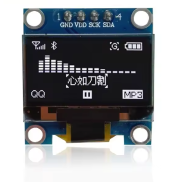
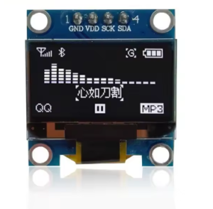
The 0.96-inch I2C OLED Display Module is a compact, high-contrast monochrome screen featuring a white-on-black display that delivers crisp, professional-looking text and graphics for your embedded projects. Powered by the SSD1306 driver IC with 128×64 pixel resolution, this tiny display packs enough resolution to show detailed sensor data, custom icons, bitmaps, and up to 8 lines of text—all while consuming minimal power .
Unlike traditional LCDs that require a power-hungry backlight, OLED (Organic Light Emitting Diode) technology allows each pixel to emit its own light. Inactive pixels are completely off, resulting in true blacks and an exceptional 10,000:1 contrast ratio that makes white text appear to “float” on a pure black background . This self-emissive design also provides wide viewing angles (>160°) and fast response times, ensuring the display remains readable from virtually any angle .
The module uses the I2C communication protocol, requiring only two data lines (SCL and SDA) to connect to your microcontroller. This 4-pin interface saves valuable I/O pins for other sensors and peripherals . With support for both 3.3V and 5V logic, it is directly compatible with Arduino, ESP32, ESP8266, Raspberry Pi, STM32, and most other development boards without level shifters .
Each module comes packaged in a transparent protective box for safe storage and protection during transport. The ultra-low power consumption (approximately 0.04W during normal operation) makes this display an ideal choice for battery-powered IoT devices, wearable projects, and portable instruments where energy efficiency is critical .
Key Features
-
128×64 Pixel Resolution: High-definition display with 128 columns and 64 rows—capable of showing detailed graphics, bitmaps, and up to 8 lines of 21 small characters (depending on font size)
-
White Monochrome OLED: Bright white pixels on a true black background provide exceptional contrast and a professional, easy-to-read appearance
-
SSD1306 Driver IC: Industry-standard controller with built-in display buffer, charge pump, and extensive software library support
-
I2C Interface: 2-wire communication protocol requires only 2 data lines (SDA and SCL), preserving valuable I/O pins for other components
-
Wide Voltage Compatibility: Operates on both 3.3V and 5V logic—directly compatible with Arduino, ESP32, ESP8266, Raspberry Pi, STM32, and most other microcontrollers
-
Ultra-Low Power Consumption: Consumes approximately 0.04W during normal operation, making it ideal for battery-powered and portable projects
-
Wide Viewing Angle: >160° visibility ensures clear readouts from almost any angle without contrast shift
-
Wide Operating Temperature: Rated for -40°C to +80°C, suitable for industrial and outdoor applications
-
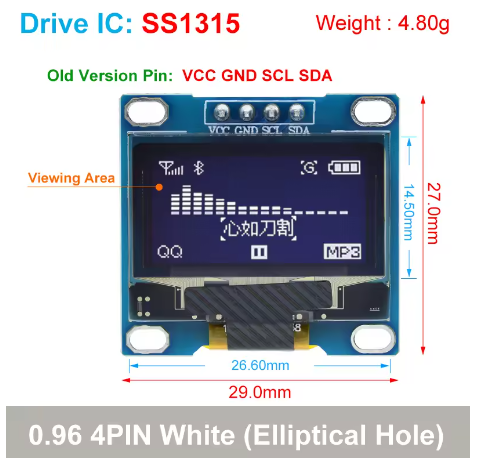
Compact Size: Small 27mm × 27mm footprint for easy integration into space-constrained projects
-
Transparent Protective Box: Includes a durable clear storage box to protect the module during transport and extend service life
Technical Specifications
Pinout & Connection Guide
The module uses a straightforward 4-pin interface, clearly labeled on the back of the PCB. Pin naming may vary slightly between manufacturers (e.g., VDD vs VCC, SCK vs SCL).
I2C Pin Mapping for Common Development Boards
Wiring Diagram (Arduino Uno)
OLED Module          →    Arduino Uno
─────────────────────────────────────
VDD (VCC)            →    5V (or 3.3V)
GND                  →    GND
SCL (SCK)            →    A5 (SCL)
SDA                  →    A4 (SDA)
⚠️ Important: While the module accepts 5V power, the I2C logic is 3.3V. Most 5V microcontrollers (like Arduino Uno) recognize 3.3V as a valid HIGH signal, so direct connection is generally safe. However, for ESP32, always use 3.3V power to avoid damaging the GPIO pins .
Usage Guide
Software Setup (Arduino IDE)
To get your OLED display up and running quickly, install the following libraries via the Arduino Library Manager (Sketch → Include Library → Manage Libraries):
These libraries are the industry standard for SSD1306 displays, providing proven reliability, extensive documentation, and a rich set of drawing functions .
Step 1: I2C Address Verification
Before running the main sketch, it’s good practice to confirm your display’s I2C address. Most modules default to 0x3C, but some may use 0x3D depending on the resistor configuration . Upload this I2C scanner sketch to find your display’s address:
#include <Wire.h>

void setup() {
  Wire.begin();
  Serial.begin(9600);
  Serial.println("I2C Scanner");
}

void loop() {
  byte error, address;
  int nDevices = 0;

  for(address = 1; address < 127; address++) {
    Wire.beginTransmission(address);
    error = Wire.endTransmission();

    if(error == 0) {
      Serial.print("I2C device found at address 0x");
      if(address < 16) Serial.print("0");
      Serial.println(address, HEX);
      nDevices++;
    }
  }

  if(nDevices == 0) Serial.println("No I2C devices found");
  delay(5000);
}
Step 2: Basic Test Sketch
#include <Wire.h>
#include <Adafruit_GFX.h>
#include <Adafruit_SSD1306.h>
#define SCREEN_WIDTH 128
#define SCREEN_HEIGHT 64
#define OLED_ADDR 0x3C
Adafruit_SSD1306 display(SCREEN_WIDTH, SCREEN_HEIGHT, &Wire, -1);
void setup() {
Serial.begin(9600);
if(!display.begin(SSD1306_SWITCHCAPVCC, OLED_ADDR)) {
Serial.println(F("SSD1306 allocation failed"));
for(;;);
}
display.clearDisplay();
display.setTextSize(2);
display.setTextColor(SSD1306_WHITE);
display.setCursor(20, 25);
display.println("OLED Ready!");
display.display();
}
void loop() {
}
Understanding the Display Buffer Workflow
The Adafruit_SSD1306 library uses a buffer-based drawing system :
-
Drawing functions (e.g., drawPixel, println, fillRect) write to an in-memory buffer, not directly to the screen
-
The screen does NOT update immediately
-
You must call display.display() to transfer the buffer contents to the actual OLED panel
This approach allows you to build complex screens without visible flickering, as the display updates only when you’re ready.
Basic Graphics Functions
display.clearDisplay();
display.drawPixel(10, 10, SSD1306_WHITE);
display.drawLine(0, 0, 127, 63, SSD1306_WHITE);
display.drawRect(10, 10, 50, 30, SSD1306_WHITE);
display.fillRect(70, 10, 40, 30, SSD1306_WHITE);
display.drawCircle(64, 32, 20, SSD1306_WHITE);
display.fillCircle(64, 32, 15, SSD1306_WHITE);
display.setTextSize(1);
display.setTextColor(SSD1306_WHITE);
display.setCursor(0, 55);
display.print("Graphics Demo");
display.display();
ESP32 / ESP8266 Example
The same libraries work for ESP32 and ESP8266. The I2C pins vary by board :
ESP32:
-
SDA: GPIO21 (default I2C)
-
SCL: GPIO22 (default I2C)
-
Use Wire.begin() without parameters for default pins
-
⚠️ Important: Connect VCC to 3.3V, not 5V, as ESP32 GPIO pins are not 5V tolerant
ESP8266 (NodeMCU):
Raspberry Pi (Python) Setup
The display also works with Raspberry Pi using Python libraries :
import board
import busio
import adafruit_ssd1306
from PIL import Image, ImageDraw, ImageFont
i2c = busio.I2C(board.SCL, board.SDA)
oled = adafruit_ssd1306.SSD1306_I2C(128, 64, i2c)
oled.fill(0)
oled.show()
oled.text("Hello Pi!", 0, 0, 1)
oled.show()
Before using the display with Raspberry Pi, enable I2C via raspi-config → Interface Options → I2C .
Power Management for Battery-Powered Projects
OLED displays are excellent for low-power applications because only lit pixels consume power. The white variant consumes slightly more power than yellow when displaying typical content due to the higher brightness of white LEDs.
Power-Saving Tips:
-
For battery-powered applications, update the display only when values change rather than continuously refreshing
-
Avoid displaying large white areas continuously to maximize battery life
-
Consider using the display’s built-in power-down mode when not needed
Q: What is the difference between this OLED and a standard LCD?
OLED pixels emit their own light, so no backlight is required. This provides true blacks (pixels are completely off), 10,000:1 contrast ratio, and >160° viewing angles . Traditional LCDs use a backlight that constantly draws power and cannot achieve true black—dark areas appear as dark gray, not pure black. OLEDs also have faster response times and lower power consumption when displaying dark content.
Q: What is the difference between the 0.96" and 0.91" OLED displays?
The 0.96″ version offers 128×64 pixels (64 rows tall), allowing up to 8 lines of small text or detailed graphics. The 0.91″ version is only 128×32 pixels (32 rows tall) , supporting about 2-3 lines of text. The 0.96″ display provides significantly more screen real estate for complex interfaces while maintaining nearly the same physical footprint.
Q: Does this display support grayscale or color?
No. This is a monochrome (single-color) display. Each pixel is either ON (white) or OFF (black). The SSD1306 driver does not support grayscale in standard configurations . However, dithering techniques (alternating patterns of on/off pixels) can simulate intermediate intensities for simple graphics.
Q: How many characters can the display show?
With the default 8×8 pixel font, the display can show approximately 16 characters × 8 lines = 128 characters total. With larger fonts (e.g., 16×16 pixels for clearer readability), fewer characters fit—about 8 characters × 4 lines = 32 characters . The display is well-suited for dashboards, status monitors, and simple menu interfaces.
Q: What is the lifespan of the OLED display?
OLEDs have a rated lifespan of approximately 20,000-30,000 hours of continuous operation (about 2.5-3.5 years). Displaying the same static image for extremely long periods (e.g., thousands of hours) can cause “burn-in” or uneven pixel wear. For typical hobbyist and intermittent use, this is not a concern .
Q: Can two displays run on the same I2C bus?
Only if they have different addresses. The SSD1306 I2C address is determined by the SA0 pin: typically 0x3C (SA0=0) or 0x3D (SA0=1). To use two displays, you would need to modify one module by moving a resistor jumper to change its address, or use an I2C multiplexer (e.g., TCA9548A) .
Q: How much current does the display draw?
Power consumption is directly related to how many and which pixels are lit:
-
All pixels off (black screen): Standby current <10µA
-
Full screen white: ~20-25mA
-
Typical text/dashboard (~25% pixels lit): ~10-15mA
White OLEDs consume approximately the same current as blue or yellow variants when displaying full-white screens, but white may use slightly more power when displaying typical mixed content.
Q: Can I adjust the display brightness?
The SSD1306 supports software brightness adjustment through the contrast control register using display.ssd1306_command(0x81) followed by a value (0-255). This command adjusts the OLED pixel drive current, which affects overall brightness and power consumption. Lower values reduce both brightness and power usage .
Q: Why does my display stay blank after power-up?
This usually indicates one of these issues :
-
Incorrect I2C address – Run the I2C scanner to confirm (most modules use 0x3C or 0x3D)
-
Wrong wiring – Verify VCC→5V (or 3.3V), GND→GND, SCL→A5, SDA→A4 for Arduino Uno
-
Loose connections – Check that jumper wires are securely connected
-
Missing display.display() call – Drawing functions write to a buffer; you must call display.display() to push the buffer to the screen
-
Power supply – Ensure your power source can deliver ~30mA
Q: Can I use both 3.3V and 5V logic?
Yes, the module is designed to work with both. The operating voltage range is 3.3V to 5.5V, so you can safely power it from either 3.3V or 5V pins on your microcontroller . However, the I2C logic levels are 3.3V, which is recognized as a valid HIGH signal by 5V microcontrollers like Arduino Uno.
Q: Why does my display flicker?
Flickering is usually caused by:
-
Insufficient power – Ensure your power supply can deliver stable voltage and current (~30mA)
-
Long I2C wires – Keep SDA/SCL wires short (<30cm) to prevent signal integrity issues
-
Missing pull-up resistors – The I2C bus requires pull-up resistors (typically 4.7kΩ to 10kΩ). Most modules include them, but if not, add external pull-ups on SDA and SCL lines to VCC
Q: What libraries are available for the SSD1306?
Popular options include :
-
Adafruit_SSD1306 (paired with Adafruit_GFX) – Most popular, well-documented, great for beginners
-
U8g2 – More fonts, advanced features, but slightly steeper learning curve
-
SSD1306Ascii – Lightweight and fast for text-only applications
For most users and projects, the Adafruit libraries are the recommended starting point due to their extensive documentation and active community support.
Q: Can I display images on this OLED?
Yes. Use tools like LCD Image Converter, Image2CPP, or online converters to transform 128×64 monochrome bitmap images into C arrays. Then use display.drawBitmap(x, y, array, width, height, color) to display them . Ensure your images are properly sized (128×64) and optimized for monochrome output.
Q: Why do I need to call display.display() after drawing commands?
The Adafruit_SSD1306 library uses a double-buffering technique. Drawing functions (like drawPixel, println, fillRect) write to an internal memory buffer, not directly to the screen. Calling display.display() transfers the entire buffer to the OLED panel in one operation. This prevents screen flicker and allows you to build complex frames efficiently .
Q: Does this library work with ESP32 and STM32?
Yes, the Adafruit_SSD1306 library supports ESP32, ESP8266, STM32, and many other platforms beyond Arduino. For ESP32, connect VCC to 3.3V (not 5V, as ESP32 is not 5V tolerant) and use the default I2C pins (GPIO21=SDA, GPIO22=SCL). The library handles the hardware differences automatically .