Product Overview
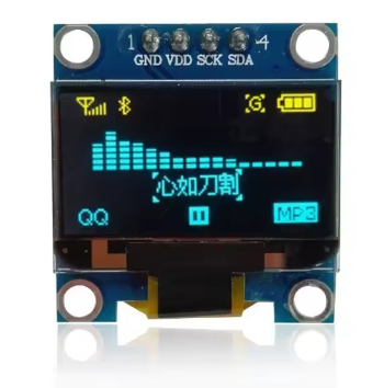
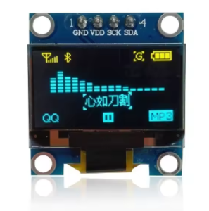
The 0.96-inch Yellow+Blue I2C OLED Display Module is a compact, high-contrast dual-color screen that adds a vibrant visual interface to your electronics projects. Featuring a distinctive yellow top section and blue bottom section powered by the SSD1306 driver IC, this 128×64 pixel display delivers crisp text, detailed graphics, and custom icons in an eye-catching two-tone format .
Unlike traditional LCDs that require a power-hungry backlight, OLED (Organic Light Emitting Diode) technology allows each pixel to emit its own light. This self-emissive design provides true blacks (inactive pixels are completely off), an exceptional 10,000:1 contrast ratio, and wide viewing angles (>160°) . The result is a professional-looking display where text and graphics appear to “float” on a pure black background—all while consuming minimal power.
The module uses the I2C communication protocol, requiring only two data lines (SCL and SDA) to connect to your microcontroller . This 4-pin interface (VCC, GND, SCL, SDA) preserves valuable I/O pins for other sensors and peripherals while simplifying wiring to a minimum .
With support for both 3.3V and 5V logic, this module is directly compatible with Arduino, ESP32, ESP8266, Raspberry Pi, STM32, and most other development boards—no level shifters required . The ultra-low power consumption (approximately 0.06W during normal operation) makes this display ideal for battery-powered IoT devices, wearable projects, smart home interfaces, data loggers, and portable instruments .
Each module comes packaged in a transparent acrylic protective box that shields the display from dust, moisture, and physical damage during transport and storage, extending its service life .
Key Features
-
128×64 Pixel Resolution: High-definition display with 128 columns and 64 rows—capable of showing detailed graphics, bitmaps, and up to 8 lines of small text (16 characters per line)
-
Yellow+Blue Dual-Color Display: Distinctive yellow top section (first 32 scan lines) and blue bottom section (remaining 32 scan lines). The color division is fixed—the display controller cannot change individual pixel colors
-
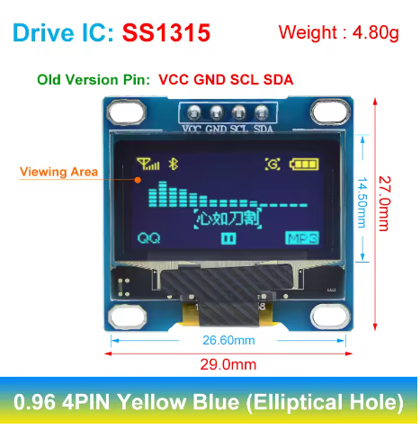
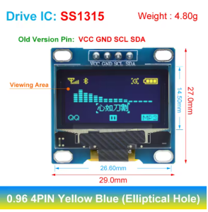
SSD1306 Driver IC: Industry-standard controller with built-in display buffer (128×64-bit SRAM), charge pump oscillator, and extensive software library support
-
I2C Interface: 2-wire communication protocol requires only 2 data lines (SDA and SCL), preserving valuable I/O pins for other components
-
Wide Voltage Compatibility: Operates on both 3.3V and 5V logic (2.8V–5.2V range)—directly compatible with Arduino, ESP32, ESP8266, Raspberry Pi, STM32, and most other microcontrollers
-
Ultra-Low Power Consumption: Consumes approximately 0.06W (typical 12-15mA at 3.3V) during normal operation—ideal for battery-powered projects. With all pixels off, standby current is <10µA
-
Wide Viewing Angle: >160° visibility ensures clear readouts from almost any angle without contrast shift
-
Self-Emitting OLED Technology: No backlight required—true blacks provide 10,000:1 contrast ratio and superior readability in all lighting conditions
-
Compact Size: Small 27.3mm × 27.3mm footprint for easy integration into space-constrained projects
-
Transparent Protective Box: Includes a durable clear acrylic case for safe storage and protection during transport
Technical Specifications
Hardware Connection Guide
The module features a 4-pin 2.54mm pitch header with clearly labeled pins on the PCB .
I2C Pin Mapping for Common Development Boards:
Wiring Diagram (Arduino Uno):
OLED Module          →    Arduino Uno
─────────────────────────────────────
VCC (VDD)            →    5V (or 3.3V)
GND                  →    GND
SCL (SCK)            →    A5 (SCL)
SDA                  →    A4 (SDA)
⚠️ Important Electrical Constraints :
-
I2C bus requires pull-up resistors (4.7kΩ recommended) on SCL and SDA lines. Most modules include these, verify on your specific board.
-
Logic reference is VCC’s voltage; ensure your microcontroller I/O matches the power supply level (3.3V for ESP32, 5V for Arduino) .
-
When using 5V microcontrollers, 3.3V logic from the module is recognized as a valid HIGH input, so no level shifter is generally needed .
-
For ESP32 or other 3.3V-only microcontrollers, never connect to 5V power—use the 3.3V pin instead to avoid damage .
Usage Guide
Color Division Notice
Please note: This display is “dual-color” only in the sense that different screen regions are physically different colors. The top section (approximately 32 rows) displays yellow pixels, while the bottom section (remaining 32 rows) displays blue pixels . This color division is fixed by the OLED panel’s physical construction—you cannot change individual pixel colors or control which pixels are yellow vs. blue through software. The display controller treats the entire screen as monochrome (pixels are either ON or OFF), with the color determined solely by the pixel’s physical location on the screen .
When planning your user interface, consider reserving the top yellow area for alerts, titles, or warnings, and using the larger blue area for data values and menus.
Software Setup (Arduino IDE)
Step 1: Install Required Libraries
Popular library options for SSD1306 displays:
-
U8g2 Library (Recommended): Supports full graphics operations (lines, boxes, circles), multiple fonts, and works with both I2C and SPI displays . Install via Library Manager: U8g2 by Oliver Kraus.
-
Adafruit Libraries (Adafruit_SSD1306 + Adafruit_GFX): Well-documented, great for beginners, provides simple graphics primitives.
-
Elecrow U8glib (specific versions): Provided by some manufacturers, may be required for certain modules .
Installation:
-
Open Arduino IDE → Sketch → Include Library → Manage Libraries
-
Search for “U8g2” (or “Adafruit SSD1306”)
-
Click Install
Step 2: I2C Address Verification (Recommended)
Most modules default to 0x3C, but it’s good practice to verify . Upload this I2C scanner sketch to find your display’s address:
#include <Wire.h>

void setup() {
  Wire.begin();
  Serial.begin(9600);
  Serial.println("I2C Scanner");
}

void loop() {
  byte error, address;
  int nDevices = 0;

  for(address = 1; address < 127; address++) {
    Wire.beginTransmission(address);
    error = Wire.endTransmission();

    if(error == 0) {
      Serial.print("I2C device found at address 0x");
      if(address < 16) Serial.print("0");
      Serial.println(address, HEX);
      nDevices++;
    }
  }

  if(nDevices == 0) Serial.println("No I2C devices found");
  delay(5000);
}
Step 3: Basic Test Sketch (U8g2 Library)
The U8g2 library is widely recommended for its excellent SSD1306 support .
#include <Arduino.h>
#include <U8g2lib.h>
#include <Wire.h>
U8G2_SSD1306_128X64_NONAME_F_SW_I2C u8g2(U8G2_R0, SCL, SDA, U8X8_PIN_NONE);
void setup(void) {
u8g2.begin();
u8g2.enableUTF8Print();
}
void loop(void) {
u8g2.clearBuffer();
u8g2.setFont(u8g2_font_luBIS08_tf);
u8g2.drawStr(10, 15, "Hello!");
u8g2.drawStr(10, 35, "Yellow + Blue");
u8g2.drawStr(10, 55, "0.96 OLED");
u8g2.sendBuffer();
delay(1000);
}
Step 4: Basic Test Sketch (Adafruit Libraries)
#include <Wire.h>
#include <Adafruit_GFX.h>
#include <Adafruit_SSD1306.h>

#define SCREEN_WIDTH 128
#define SCREEN_HEIGHT 64
#define OLED_ADDR 0x3C

Adafruit_SSD1306 display(SCREEN_WIDTH, SCREEN_HEIGHT, &Wire, -1);

void setup() {
  Serial.begin(9600);

  if(!display.begin(SSD1306_SWITCHCAPVCC, OLED_ADDR)) {
    Serial.println(F("SSD1306 allocation failed"));
    for(;;);
  }

  display.clearDisplay();
  display.setTextSize(1);
  display.setTextColor(SSD1306_WHITE);
  display.setCursor(10, 15);
  display.println("Hello!");
  display.setCursor(10, 35);
  display.println("Yellow + Blue");
  display.setCursor(10, 55);
  display.println("0.96 OLED");
  display.display();
}

void loop() {}
Using the Display with Different Libraries
U8g2 Library Settings :
Tested configurations for U8g2 with SSD1306:
-
U8G2_SSD1306_128X64_NONAME_F_SW_I2C u8g2(U8G2_R0, SCL, SDA, U8X8_PIN_NONE); → Software I2C, works with any GPIO pins
-
U8G2_SSD1306_128X64_NONAME_1_SW_I2C u8g2(U8G2_R0, SCL, SDA, U8X8_PIN_NONE); → Uses reduced buffer mode (smaller RAM footprint)
Display buffer methods:
-
u8g2.clearBuffer() → Clear internal buffer (pixels off)
-
u8g2.sendBuffer() → Transfer buffer to the screen
-
Use u8g2.firstPage() / u8g2.nextPage() loop for complex graphics
Key U8g2 Functions:
u8g2.setFont(fontName);
u8g2.setDrawColor(1);
u8g2.drawStr(x, y, "text");
u8g2.drawBox(x, y, w, h);
u8g2.drawCircle(x, y, r);
Displaying Text and Graphics
The U8g2 library supports many font sizes and styles :
u8g2.setFont(u8g2_font_5x7_tf);
u8g2.setFont(u8g2_font_7x14_tf);
u8g2.setFont(u8g2_font_10x20_tf);
u8g2.drawFrame(10, 10, 50, 30);
u8g2.drawBox(70, 10, 40, 30);
u8g2.drawCircle(64, 45, 10);
Raspberry Pi (Python) Setup
The display also works with Raspberry Pi using Python libraries:
import board
import busio
import adafruit_ssd1306
from PIL import Image, ImageDraw, ImageFont
i2c = busio.I2C(board.SCL, board.SDA)
oled = adafruit_ssd1306.SSD1306_I2C(128, 64, i2c)
oled.fill(0)
oled.show()
oled.text("Hello Pi!", 0, 0, 1)
oled.show()
Note: Before using with Raspberry Pi, enable I2C via sudo raspi-config → Interface Options → I2C.
Power Management for Battery-Powered Projects
OLED displays are excellent for low-power applications because only lit pixels consume power . The Yellow+Blue variant’s power consumption is approximately the same as monochrome variants when displaying typical mixed content.
Power-Saving Tips:
-
Use display.ssd1306_command(0xAE) to turn the display OFF when not actively updating, and 0xAF to turn back ON
-
Update the display only when values change rather than continuously refreshing
-
Avoid displaying large white or high-density areas continuously to maximize battery life
-
For battery-powered applications, consider powering from 3.3V for slightly lower consumption
Understanding the Display Buffer Workflow
Most libraries use a buffer-based drawing system:
-
Drawing functions (e.g., drawPixel, drawStr, fillRect) write to an in-memory buffer
-
The screen does NOT update immediately
-
You must call display.display() (Adafruit) or sendBuffer() / nextPage() (U8g2) to transfer the buffer contents to the actual OLED panel
This double-buffering technique prevents screen flicker and allows you to build complex frames efficiently.
Adafruit workflow:
display.clearDisplay();
display.display();
U8g2 workflow:
u8g2.clearBuffer();
u8g2.sendBuffer();
Q: What is the difference between this OLED and a standard LCD?
OLED pixels emit their own light, so no backlight is required. This provides true blacks (inactive pixels are completely off), 10,000:1 contrast ratio, and >160° viewing angles . Traditional LCDs use a backlight that constantly draws power and cannot achieve true black—dark areas appear as dark gray, not pure black. OLEDs also have faster response times and significantly lower power consumption when displaying dark content.
Q: What is the difference between the 0.96" Yellow+Blue and 0.91" OLED displays?
The 0.96″ version offers 128×64 pixels (64 rows tall) , allowing up to 8 lines of small text or detailed graphics. The 0.91″ version is only 128×32 pixels (32 rows tall) , supporting about 2-3 lines of text. The 0.96″ dual-color provides the same vertical resolution as the monochrome version but with distinctive yellow/blue regions .
Q: How does the Yellow+Blue color work? Is it truly a color display?
No. The Yellow+Blue display is still a monochrome display—individual pixels are either ON or OFF (emitting light when ON, black when OFF). The difference is that the OLED panel is physically manufactured with two distinct materials: the top 32 scan lines emit light in the yellow spectrum, while the bottom 32 scan lines emit blue . You cannot change the color of individual pixels—the color is determined solely by the pixel’s vertical position on the screen. This creates a striking two-tone effect ideal for separating UI regions (e.g., yellow title bar, blue content area).
Q: Does this display support grayscale or color mixing?
No. This is a monochrome display with region-specific colors. The SSD1306 driver does not support grayscale in standard configurations . The only way to simulate intermediate intensities is through dithering (alternating patterns of on/off pixels), but this is complex and rarely used for these displays.
Q: Can I change the color of individual pixels or the color ratio?
No. The color division (yellow top, blue bottom) is fixed by the OLED panel’s physical construction . You cannot change which pixels are yellow vs. blue through software. The display controller treats all pixels identically; the displayed color is determined solely by the pixel’s physical location on the screen.
Q: How many characters can the display show?
With the default 8×8 pixel font, the display can show approximately 16 characters × 8 lines = 128 characters total . With larger fonts (e.g., 16×16 pixels for better readability), fewer characters fit—about 8 characters × 4 lines = 32 characters. The display is well-suited for dashboards, status monitors, and simple menu interfaces. Because the color division is at row 32, text can be clearly separated (yellow at top, blue at bottom) for visual organization.
Q: What is the lifespan of the OLED display?
OLEDs have a rated lifespan of approximately 20,000-30,000 hours of continuous operation (about 2.5-3.5 years). Displaying the same static image for extremely long periods (e.g., thousands of hours) can cause “burn-in” or uneven pixel wear, which may be more noticeable on dual-color displays due to differences in material aging rates.
Q: What is a charge pump and why is it needed?
The SSD1306 includes an internal charge pump circuit that generates the higher voltage required to drive the OLED pixels from the 3.3V/5V logic supply . Without this, the display would require an external high-voltage supply. The library’s SSD1306_SWITCHCAPVCC parameter enables this internal charge pump .
Q: Can two displays run on the same I2C bus?
Only if they have different addresses. The SSD1306 I2C address is typically fixed at 0x3C (write: 0x78) . To use two displays, you would need to modify one module by moving a resistor jumper to change its address to 0x3D, or use an I2C multiplexer (e.g., TCA9548A).
Q: How much current does the display draw?
Power consumption is directly related to how many and which pixels are lit :
-
All pixels off (black screen): Standby current <10µA (display off)
-
Typical text/dashboard (~25% pixels lit): ~9-12mA
-
Full screen white: ~20-25mA
The Yellow+Blue variant’s power consumption is approximately the same as monochrome variants when displaying typical mixed content because each lit pixel consumes power regardless of its color.
Q: Can I adjust the display brightness?
The SSD1306 supports software brightness adjustment through the contrast control register using display.ssd1306_command(0x81) followed by a value (0-255). Lower values reduce both brightness and power consumption.
Q: What is the transparent box used for?
The transparent acrylic protective box provides safe storage for the module, protecting it from dust, moisture, and physical damage during transport and when not in use . The case is often DIY assembly—remember to remove the protective film from both sides of the acrylic pieces before final assembly.
Q: Why does my display stay blank after power-up?
This usually indicates one of these issues :
-
Incorrect I2C address – Run the I2C scanner to confirm (most modules use 0x3C)
-
Wrong wiring – Verify VCC→5V (or 3.3V), GND→GND, SCL→SCL, SDA→SDA
-
Loose connections – Check that jumper wires are securely connected
-
Missing display.display() or sendBuffer() call – Libraries use double-buffering; you must call the appropriate transfer function
-
Insufficient power – Ensure your power source can deliver ~30mA
-
Reset sequence – The module doesn’t have a dedicated RESET pin (it’s internally pulled high), but ensure power-on timing isn’t too slow
Q: Can I use both 3.3V and 5V logic?
Yes, the module is designed to work with both. The operating voltage range is 2.8V to 5.2V, so you can safely power it from either 3.3V or 5V pins on your microcontroller . However, the I2C logic reference is VCC’s voltage. When using 5V power with 3.3V logic microcontrollers (ESP32), the logic levels are generally compatible (3.3V is recognized as HIGH by the SSD1306). When using 3.3V power with 5V logic microcontrollers, ensure your specific microcontroller’s I/O thresholds are met (3.3V logic is typically recognized as HIGH by 5V devices).
⚠️ Important for ESP32: Never connect VCC to 5V—use the 3.3V pin only. ESP32 GPIO pins are not 5V tolerant, and applying 5V power may damage the board .
Q: Why does my display flicker?
Flickering is usually caused by:
-
Insufficient power – Ensure your power supply can deliver stable voltage and current (~30mA)
-
Long I2C wires – Keep SDA/SCL wires short (<30cm) to prevent signal integrity issues
-
Missing or weak pull-up resistors – I2C bus requires pull-up resistors (typically 4.7kΩ on most modules). If absent, add external pull-ups on SDA and SCL lines to VCC
Q: What are the logic level thresholds for the I2C pins?
According to the SSD1306 specifications :
-
Input LOW (VIL): ≤ 0.2 × VCC (e.g., ≤1.0V at 5V VCC)
-
Input HIGH (VIH): ≥ 0.8 × VCC (e.g., ≥4.0V at 5V VCC)
This means at 5V VCC, the module expects HIGH signals above 4.0V, which standard 5V Arduino outputs can provide. At 3.3V VCC, HIGH threshold is ≥2.64V, easily met by 3.3V microcontrollers.
Q: What libraries are available for the SSD1306?
Popular options include :
-
U8g2 – Most feature-rich, supports many fonts, graphics operations, and works with both I2C and SPI displays. Recommended for complex graphics and professional interfaces
-
Adafruit_SSD1306 (paired with Adafruit_GFX) – Simpler, well-documented, great for beginners and basic text/graphics
-
U8glib – Legacy library, still functional but U8g2 is recommended for new projects
-
SSD1306Ascii – Lightweight, text-only, minimal RAM footprint (good for Arduino Uno)
Q: Why do I need to call display.display() or sendBuffer() after drawing commands?
Most libraries use a double-buffering technique . Drawing functions write to an internal memory buffer, not directly to the screen. Calling the transfer function sends the entire buffer to the OLED panel in one operation. This eliminates screen flicker and allows you to build complex frames without visual tearing. The buffer is typically 128×64 bits = 1024 bytes of SRAM, which fits comfortably on most microcontrollers.
Q: Can I display images on this OLED?
Yes. Use tools like LCD Image Converter, Image2CPP, or online converters to transform 128×64 monochrome bitmap images into C arrays. Then use display.drawBitmap(x, y, array, width, height, color) (Adafruit) or convert the array to the proper format for U8g2. Remember that the top 32 lines will display in yellow, the bottom 32 in blue, regardless of the image content. Plan your UI layout accordingly—place important graphics or text that benefit from yellow highlighting in the top area.
Q: Does the library work with ESP32 and STM32?
Yes, both U8g2 and Adafruit libraries support ESP32, ESP8266, STM32, and many other platforms beyond Arduino. For ESP32, connect VCC to 3.3V (not 5V, as ESP32 is not 5V tolerant) and use the default I2C pins (GPIO21=SDA, GPIO22=SCL). The library handles the hardware differences automatically .
Q: Can I use SPI instead of I2C with this module?
No. This specific 4-pin module is hardwired for I2C mode only. The SSD1306 chip supports SPI (3-wire and 4-wire), but those pins are not broken out on this board . For SPI connectivity, you would need the 7-pin version of the SSD1306 module.
Q: What can I build with this Yellow+Blue OLED display?
Popular applications include :
-
IoT Sensor Stations: Display temperature, humidity, and pressure with yellow alert section and blue data section
-
Smart Home Control Panels: Show system status and device controls with color-coded regions
-
Handheld Gaming: Display scores and game status with yellow for warnings/points and blue for game area
-
Data Loggers: Visualizing real-time sensor data with chronological scrolling
-
Diagnostic Tools: Battery testers, oscilloscope displays, spectrum analyzers
-
Wearable Devices: Fitness trackers, smart watches where compact size matters
-
Industrial Control Panels: Status indicators and process monitoring with visual separation of warnings vs. data
Q: Why choose the Yellow+Blue version over monochrome (white/blue/yellow)?
The dual-color design provides visual hierarchy without any software overhead—you get distinct colors for different UI sections simply by placing content at specific screen locations . This makes interfaces more intuitive (e.g., yellow status bar + blue content area) and visually appealing, with no extra code or processing power required. It’s particularly useful for:
-
Alert displays (yellow area for warnings, blue for normal data)
-
Menu systems (yellow title bar, blue menu items)
-
Gaming (yellow scores, blue game field)
-
Instrumentation (yellow alarm section, blue measurement area)