Product Overview
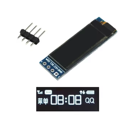
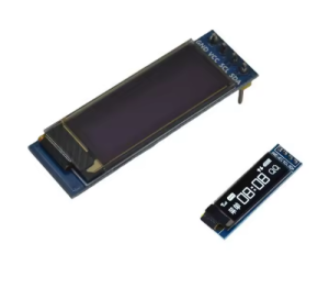
The 0.91-inch I2C OLED Display Module is a compact, high-contrast monochrome graphic display designed for embedded projects requiring crisp visual output without consuming excessive power or I/O pins. Powered by the SSD1306 driver IC and featuring a clear 128×32 pixel resolution, this display delivers bright white text and simple graphics on a true black background .
OLED (Organic Light Emitting Diode) technology requires no backlight, as each pixel emits its own light. This self-emissive design provides true blacks (inactive pixels are completely off), excellent contrast, and wide viewing angles – ensuring the display remains readable from virtually any angle .
The module uses the ultra-simple 4-pin I2C interface (VCC, GND, SCL, SDA), requiring only two data lines to connect to your microcontroller. This preserves valuable I/O pins for other sensors and peripherals. With support for both 3.3V and 5V logic, it is directly compatible with Arduino, ESP32, ESP8266, Raspberry Pi, STM32, and most other development boards – no level shifters required .
With an ultra-narrow PCB design (approximately 38×12mm), this module is specifically suited for wearable devices, mini consoles, IoT gadgets, and other space-constrained projects .
Key Features
-
0.91-Inch Active Area: 128×32 pixel resolution with a compact 38×12mm PCB – fits easily into tight spaces
-
White Monochrome OLED: Clean white pixels on true black background provide excellent contrast and professional appearance
-
SSD1306 Driver IC: Industry-standard controller with built-in display buffer and extensive library support
-
I2C Interface: 4-pin connection (VCC, GND, SCL, SDA) requires only 2 data lines – saves valuable I/O pins
-
Wide Voltage Compatibility: Operates on DC 3.3V – 5V, compatible with both 5V (Arduino) and 3.3V (ESP32/ESP8266) logic
-
Ultra-Low Power Consumption: 13-25mA typical operating current; unlit pixels draw no power – ideal for battery-powered projects
-
Wide Operating Temperature: Rated for -40°C to +85°C, suitable for demanding environments
-
Comprehensive Library Support: Compatible with Adafruit_SSD1306, U8g2, and MicroPython libraries
Technical Specifications
Pinout & Connection Guide
The 4-pin I2C interface is extremely simple, making it perfect for beginners and rapid prototyping.
Pin Definitions (4-Pin)
I2C Pin Mapping for Common Development Boards
Wiring Diagram (Arduino Uno)
OLED Module          →    Arduino Uno
─────────────────────────────────────
VCC                  →    5V
GND                  →    GND
SCL                  →    A5 (SCL)
SDA                  →    A4 (SDA)
Note: The module’s built-in voltage regulator accepts both 3.3V and 5V power, so direct connection is safe for both 5V and 3.3V microcontrollers .
Usage Guide
Software Setup (Arduino IDE)
Step 1: Install Required Libraries
You need two libraries – one for the display driver and one for graphics primitives.
Method 1: Adafruit Libraries (Recommended for Beginners)
-
Open Arduino IDE → Sketch → Include Library → Manage Libraries
-
Search for and install:
Method 2: U8g2 Library (More Fonts)
Step 2: I2C Address Verification
Most 0.91″ I2C OLED modules use address 0x3C. You can verify by running this scanner :
#include <Wire.h>

void setup() {
  Wire.begin();
  Serial.begin(9600);
  Serial.println("I2C Scanner");
}

void loop() {
  byte error, address;
  int nDevices = 0;

  for(address = 1; address < 127; address++) {
    Wire.beginTransmission(address);
    error = Wire.endTransmission();

    if(error == 0) {
      Serial.print("I2C device found at address 0x");
      if(address < 16) Serial.print("0");
      Serial.println(address, HEX);
      nDevices++;
    }
  }

  if(nDevices == 0) Serial.println("No I2C devices found");
  delay(5000);
}
Step 3: Basic Test Sketch (Adafruit Libraries)
#include <Wire.h>
#include <Adafruit_GFX.h>
#include <Adafruit_SSD1306.h>
#define SCREEN_WIDTH 128
#define SCREEN_HEIGHT 32
#define OLED_RESET -1
Adafruit_SSD1306 display(SCREEN_WIDTH, SCREEN_HEIGHT, &Wire, OLED_RESET);
void setup() {
Serial.begin(9600);
if(!display.begin(SSD1306_SWITCHCAPVCC, 0x3C)) {
Serial.println(F("SSD1306 allocation failed"));
for(;;);
}
display.clearDisplay();
display.setTextSize(1);
display.setTextColor(SSD1306_WHITE);
display.setCursor(0, 0);
display.println("0.91 OLED");
display.println("128x32 Ready!");
display.display();
}
void loop() {
}
Step 4: Alternative using U8g2 Library
#include <Arduino.h>
#include <U8g2lib.h>
#include <Wire.h>

U8G2_SSD1306_128X32_NONAME_F_HW_I2C u8g2(U8G2_R0, U8X8_PIN_NONE);

void setup() {
  u8g2.begin();
  u8g2.setFont(u8g2_font_ncenB08_tr);
}

void loop() {
  u8g2.firstPage();
  do {
    u8g2.drawStr(0, 15, "0.91 OLED");
    u8g2.drawStr(0, 30, "128x32 Ready!");
  } while ( u8g2.nextPage() );
  delay(1000);
}
Raspberry Pi Setup (Python)
-
Enable I2C via raspi-config → Interface Options → I2C → Yes
-
Install required libraries:
sudo apt-get install python3-pip
pip3 install adafruit-circuitpython-ssd1306
-
Python example code:
import board
import busio
import adafruit_ssd1306
from PIL import Image, ImageDraw, ImageFont
i2c = busio.I2C(board.SCL, board.SDA)
oled = adafruit_ssd1306.SSD1306_I2C(128, 32, i2c)
oled.fill(0)
oled.show()
oled.text("0.91 OLED", 0, 0, 1)
oled.text("128x32 Ready!", 0, 15, 1)
oled.show()
Understanding the Display Buffer Workflow
Most OLED libraries use a buffer-based drawing system :
-
Drawing functions (e.g., drawPixel, println, fillRect) write to an in-memory buffer, not directly to the screen
-
The screen does NOT update immediately
-
You must call display.display() (Adafruit) to transfer buffer contents to the OLED panel
This double-buffering technique prevents screen flicker and allows you to build complex frames efficiently.
Power Management for Battery-Powered Projects
OLED displays are excellent for low-power applications because only lit pixels consume power .
Power-Saving Tips:
-
Update the display only when values change rather than continuously refreshing
-
Use display.ssd1306_command(0xAE) to turn the display OFF when not actively needed
-
Use display.ssd1306_command(0xAF) to turn it back ON
Q: What is the difference between this 0.91" OLED and the 0.96" version?
The 0.91″ display has a resolution of 128×32 pixels, offering 32 vertical pixels (about 2-4 lines of text). The 0.96″ version typically has 128×64 pixels, offering 64 vertical pixels (about 5-8 lines of text). Choose the 0.91″ for extremely compact projects, and the 0.96″ for more screen real estate
Q: What is the default I2C address for this display?
The default I2C address is 0x3C, which should work for most modules. If you have trouble detecting it, run the I2C scanner sketch to confirm the address .
Q: Can I use this display with a 5V Arduino Uno directly?
Yes. The module includes an onboard voltage regulator that accepts both 3.3V and 5V power. Connect VCC to 5V, GND to GND, SCL to A5, and SDA to A4 – no level shifters required .
Q: How many characters can the display show?
With the default 8×8 pixel font, approximately 16 characters × 4 lines = 64 characters total. With larger fonts (e.g., 16×16 pixels), about 8 characters × 2 lines = 16 characters. The display is best suited for sensor readouts, status messages, and simple menus .
Q: Why does my display stay blank after power-up?
Check these common issues:
-
Wrong I2C address – Some modules use 0x3D instead of 0x3C
-
Wiring – Verify VCC→5V (or 3.3V), GND→GND, SCL→A5, SDA→A4
-
Incorrect I2C port – Some Arduino boards have multiple I2C ports; verify you’re using the correct one in your code
-
Missing display.display() call – Drawing functions write to a buffer; you must call display.display() to push the buffer to the screen
-
Power supply – Ensure your power source can deliver ~30mA
Q: Can I use this display with ESP32 or ESP8266?
Yes. Both ESP32 and ESP8266 use 3.3V logic, which matches the display’s requirements. Connect VCC to 3.3V, GND to GND, SCL to appropriate pins, and SDA to appropriate pins. The same libraries work on these platforms .
Q: Is the 0.91" OLED readable in direct sunlight?
OLEDs have excellent contrast, making them more readable than traditional LCDs in bright conditions. However, like all emissive displays, direct bright sunlight may reduce perceived contrast. The white color provides good visibility .
Q: How do I display Chinese characters or custom fonts?
Chinese characters and custom fonts require a “font extraction” tool to convert text into bitmap data arrays. The U8g2 library supports UTF-8 encoding and includes Chinese fonts (u8g2_font_wqy12_t). Enable with u8g2.enableUTF8Print() and use the appropriate font .
Q: What is the lifespan of the OLED display?
Rated lifespan is approximately 20,000-30,000 hours of continuous operation (about 2.5-3.5 years). Avoid displaying static images for extremely long periods to prevent uneven pixel wear (“burn-in”). For typical intermittent hobbyist use, this is not a concern .
Q: Can I use this display with Raspberry Pi?
Yes. Enable I2C via raspi-config, then connect VCC to 3.3V (Pin 1), GND to GND, SCL to GPIO3 (Pin 5), and SDA to GPIO2 (Pin 3). Use Python libraries like adafruit-circuitpython-ssd1306 or luma.oled .
Q: What is the power consumption of this display?
Typically 13mA at 3V and about 25mA at 5V when the screen is fully lit. When all pixels are off, consumption drops to ~2mA, and in sleep mode it can go below 5µA. This makes it excellent for battery-powered projects .
Q: Can I use this display for displaying graphs or simple animations?
Yes. The 128×32 resolution can display simple bar graphs, scrolling text, and basic animations. For optimal performance, use the _F_ (full buffer) constructors in U8g2 or the standard Adafruit buffer with frequent updates .