Product Overview
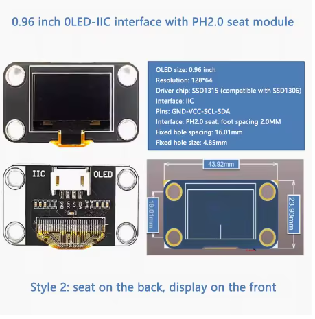
The 0.96-inch White OLED Display Module is a compact, high-contrast monochrome graphic display designed for embedded projects requiring crisp visual output without consuming excessive power or I/O pins. Powered by the SH1106 driver IC and featuring a clear 128×64 pixel resolution, this display delivers bright white text, detailed graphics, and custom icons on a true black background .
OLED (Organic Light Emitting Diode) technology requires no backlight, as each pixel emits its own light. This self-emissive design provides true blacks (inactive pixels are completely off), exceptional contrast, and wide viewing angles—ensuring the display remains readable from virtually any angle .
The module features a convenient PH2.0 connector on the back, making it easy to connect using standard 4-pin JST cables. It uses the I2C (IIC) interface, requiring only two data lines (SDA and SCL) to connect to your microcontroller . This preserves valuable I/O pins for other sensors and peripherals.
With support for both 3.3V and 5V logic, it is directly compatible with Arduino, ESP32, ESP8266, STM32, and most other development boards – no level shifters required .
Key Features
-
PH2.0 Connector (Back-Mounted): Convenient JST connector on the back for easy plug-and-play installation using standard 4-pin cables
-
0.96-Inch Active Area: 128×64 pixel resolution with 21.74 × 10.86mm active area – compact yet highly readable
-
White Monochrome OLED: Clean white pixels on true black background provide excellent contrast and professional appearance
-
SH1106 Driver IC: Industry-standard controller with built-in 128×64-bit SRAM display buffer and support for I2C interface
-
I2C Interface: 4-pin connection (VCC, GND, SCL, SDA) with default address 0x3C – requires only 2 data lines
-
Wide Voltage Compatibility: Operates on DC 3.3V – 5V, compatible with both 5V (Arduino) and 3.3V (ESP32/ESP8266) systems
-
Ultra-Low Power Consumption: 50% display pattern draws only 10mA typical; unlit pixels draw no power – ideal for battery-powered projects
-
Wide Operating Temperature: Rated for -40°C to +80°C, suitable for industrial and outdoor applications
Technical Specifications
Pinout & Connection Guide
The module features a PH2.0 connector on the back with the following 4-pin configuration :
I2C Pin Mapping for Common Development Boards
Wiring Diagram (Arduino Uno)
OLED Module          →    Arduino Uno
─────────────────────────────────────
VCC                  →    5V
GND                  →    GND
SCL                  →    A5 (SCL)
SDA                  →    A4 (SDA)
PH2.0 Connector Information
The PH2.0 connector is a 2.0mm pitch JST-compatible connector commonly used for battery connections and display modules. The back-mounted connector allows easy connection using standard 4-pin cables, keeping your wiring neat and organized.
SH1106 Driver Note
This 0.96″ display uses the SH1106 driver IC. The SH1106 has internal RAM of 132×64 pixels, while the visible area is 128×64 pixels . This is different from the SSD1306 driver found on some 0.96″ displays. For library compatibility:
-
U8g2 library works with both SH1106 and SSD1306 – recommended
-
Adafruit_SSD1306 library may still work, but may have minor display artifacts (incorrect column start address)
-
When using libraries, ensure you select SH1106 support if available
Key difference: The SH1106 requires a column start address of 0x02 (unlike SSD1306’s 0x00). Most modern libraries handle this automatically .
Usage Guide
Software Setup (Arduino IDE)
Step 1: Install Required Libraries
The U8g2 library by Oliver Kraus is the most reliable choice for SH1106 displays, offering excellent support and many font options.
-
Open Arduino IDE → Sketch → Include Library → Manage Libraries
-
Search for “U8g2” by Oliver Kraus
-
Click Install
Alternative Libraries:
Step 2: I2C Address Verification
Most modules use address 0x3C. Some may use 0x3D depending on configuration . Run this I2C scanner to verify:
#include <Wire.h>

void setup() {
  Wire.begin();
  Serial.begin(9600);
  Serial.println("I2C Scanner");
}

void loop() {
  byte error, address;
  int nDevices = 0;

  for(address = 1; address < 127; address++) {
    Wire.beginTransmission(address);
    error = Wire.endTransmission();

    if(error == 0) {
      Serial.print("I2C device found at address 0x");
      if(address < 16) Serial.print("0");
      Serial.println(address, HEX);
      nDevices++;
    }
  }

  if(nDevices == 0) Serial.println("No I2C devices found");
  delay(5000);
}
Step 3: Basic Test Sketch (U8g2 Library)
#include <Arduino.h>
#include <U8g2lib.h>
#include <Wire.h>
U8G2_SH1106_128X64_NONAME_F_HW_I2C u8g2(U8G2_R0, U8X8_PIN_NONE);
void setup() {
u8g2.begin();
u8g2.enableUTF8Print();
u8g2.setFont(u8g2_font_ncenB08_tr);
}
void loop() {
u8g2.firstPage();
do {
u8g2.drawStr(0, 15, "0.96 OLED");
u8g2.drawStr(0, 35, "128x64");
u8g2.drawStr(0, 55, "SH1106 - I2C");
} while ( u8g2.nextPage() );
delay(1000);
}
Step 4: Alternative Using Adafruit Library
#include <Wire.h>
#include <Adafruit_GFX.h>
#include <Adafruit_SSD1306.h>
#define SCREEN_WIDTH 128
#define SCREEN_HEIGHT 64
#define OLED_RESET -1
Adafruit_SSD1306 display(SCREEN_WIDTH, SCREEN_HEIGHT, &Wire, OLED_RESET);
void setup() {
if(!display.begin(SSD1306_SWITCHCAPVCC, 0x3C)) {
Serial.println(F("SSD1306 allocation failed"));
for(;;);
}
display.clearDisplay();
display.setTextSize(1);
display.setTextColor(SSD1306_WHITE);
display.setCursor(0, 0);
display.println("0.96 OLED");
display.println("128x64 Ready!");
display.display();
}
void loop() {}
Raspberry Pi Setup (Python)
-
Enable I2C: sudo raspi-config → Interface Options → I2C → Yes
-
Install required libraries:
sudo apt-get install python3-pip
pip3 install luma.oled
-
Python example code:
from luma.core.interface.serial import i2c
from luma.oled.device import sh1106
from luma.core.render import canvas
serial = i2c(port=1, address=0x3C)
device = sh1106(serial, width=128, height=64)
with canvas(device) as draw:
draw.rectangle(device.bounding_box, outline="white", fill="black")
draw.text((10, 20), "0.96 OLED", fill="white")
draw.text((10, 40), "128x64 Ready!", fill="white")
Power Management for Battery-Powered Projects
OLED displays are excellent for low-power applications because only lit pixels consume power .
Power-Saving Tips:
Q: What is the default I2C address of this display?
The default I2C address is 0x3C. Some modules may support 0x3D via resistor configuration. If you have trouble detecting the device, run the I2C scanner sketch to confirm the address
Q: Can I use this display with a 5V Arduino Uno directly?
Yes. The module is rated for 3.3V-5V operation and has been tested to work reliably at 5V . Connect VCC to 5V, GND to GND, SCL to A5, and SDA to A4 – no level shifters required.
Q: What is the PH2.0 connector and why is it convenient?
The PH2.0 connector is a 2.0mm pitch JST-compatible connector. The back-mounted connector allows you to use standard 4-pin JST cables for plug-and-play installation without soldering. The back placement keeps the front of your project clean and uncluttered.
Q: Why does my display stay blank after power-up?
Check these common issues:
-
Wrong I2C address – Run the I2C scanner sketch to verify (should be 0x3C)
-
Wiring – Verify VCC→5V (or 3.3V), GND→GND, SCL→SCL, SDA→SDA
-
Program control required – OLED displays do not light up from power alone; they must be initialized by code
-
Power supply – Ensure your power source can deliver ~30mA
Q: What is the difference between SH1106 and SSD1306?
The SH1106 driver (used on this module) has internal RAM of 132×64 pixels, while the visible area is 128×64 pixels. The SH1106 requires a column start address of 0x02, while SSD1306 uses 0x00 . Most modern libraries (U8g2, Adafruit) handle this automatically, but code written exclusively for SSD1306 may need adjustment.
Q: Can I connect the display to both 3.3V and 5V systems?
Yes. The module is rated for 3.3V – 5V DC. You can use it with 3.3V systems (ESP32, Raspberry Pi) or 5V systems (Arduino Uno/Mega). The built-in voltage regulation handles both .
Q: What is the lifespan of the OLED display?
In normal working conditions, OLED modules typically last 50,000 hours (about 5.7 years) . Avoid displaying static images for extremely long periods to prevent uneven pixel wear (“burn-in”). For typical intermittent hobbyist use, this is not a concern.
Q: How do I use this display with an ESP32 or ESP8266?
Yes. Both ESP32 and ESP8266 use 3.3V logic, which is directly compatible. Connect VCC to 3.3V, GND to GND, and SCL/SDA to the appropriate I2C pins (GPIO21/GPIO22 for ESP32; GPIO4/GPIO5 for ESP8266) . The U8g2 library works on these platforms with the same code.
Q: Can I display Chinese characters or custom fonts?
Yes. The U8g2 library supports UTF-8 encoding and includes various fonts. Enable with u8g2.enableUTF8Print() and use fonts like u8g2_font_wqy12_t. For custom fonts, tools like LCD Image Converter can convert text into bitmap data arrays.
Q: How do I prevent OLED burn-in?
Avoid displaying the same static image for extended periods . For long-term installations, consider:
-
Shifting displayed content periodically
-
Turning off the display when not in use (send command 0xAE)
-
Using sleep mode in your code between updates
-
Implementing screen savers for static interfaces
Q: What is the operating temperature range of this display?
The module is rated for -40°C to +80°C operating temperature , making it suitable for industrial and outdoor applications including automotive and cold storage environments.
Q: Does this display require any external components to work?
No, the module is self-contained with all necessary components including pull-up resistors for I2C communication. Simply connect power and I2C lines to your microcontroller and it’s ready to use.
Q: Can I use this display for simple animations?
Yes. The display refresh rate is sufficient for simple animations, scrolling text, and dynamic content. For optimal performance, use the U8g2 library’s full buffer mode, which provides smoother updates.
Q: Can I control the display I2C address?
The default address is 0x3C. On some modules, you can change the address by modifying resistor connections to select 0x3D . Check your module’s documentation for details.
Q: The screen is working but the display is too dim. What should I check?
First, verify VCC is providing adequate voltage (3.3V or 5V). You can also adjust contrast in software using library functions like u8g2.setContrast(value) or display.setContrast(value). Also ensure the protective film has been removed from the OLED surface.