Product Overview
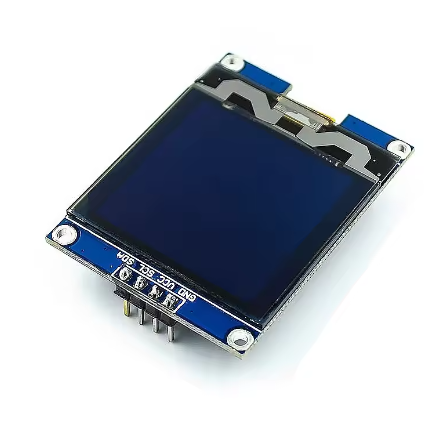
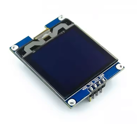
The 1.5-inch 128×128 White OLED Display Module is a high-density graphic display designed for embedded projects that require crisp, detailed visual output in a compact form factor. Driven by the SH1107 controller, this square-format display features a sharp 128×128 pixel resolution with bright white monochrome pixels on a true black background.
OLED (Organic Light Emitting Diode) technology requires no backlight, as each pixel emits its own light. This self-emissive design provides true blacks (inactive pixels are completely off), excellent contrast, and wide viewing angles — ensuring the display remains readable from virtually any angle while consuming minimal power.
The module uses the I2C interface, requiring only two data lines (SDA and SCL) to connect to your microcontroller. This preserves valuable I/O pins for other sensors and peripherals. With support for both 3.3V and 5V logic, it is directly compatible with ESP32, ESP8266, STM32, Raspberry Pi, and many other development boards – no level shifters required.
Important Memory Consideration: This display requires approximately 2KB of SRAM just for the display buffer (128×128 ÷ 8 = 2,048 bytes). As such, it cannot be used with memory-constrained microcontrollers like the Arduino Uno (ATmega328P) which has only 2KB total SRAM . For reliable operation, use a microcontroller with 16KB or more RAM such as ESP32, ESP8266, STM32, Teensy, SAMD21, SAMD51, or Raspberry Pi .
Key Features
-
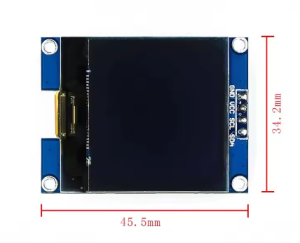
1.5-Inch Square Active Area: 128×128 pixel resolution with approximately 20mm × 20mm active area – perfect for square dashboard displays, menus, and graphics
-
Higher Resolution than Standard OLEDs: Offers 4× the pixels of common 128×64 OLEDs (16,384 vs 8,192 pixels) for significantly more detailed graphics and text
-
White Monochrome OLED: Clean white pixels on true black background provide excellent contrast and professional appearance
-
SH1107 Driver IC: Advanced controller designed specifically for higher-resolution 128×128 displays with built-in display buffer
-
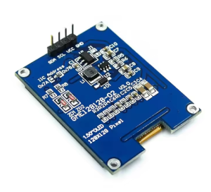
I2C Interface: 4-pin connection (GND, VCC, SCL, SDA) – requires only 2 data lines, saving GPIO pins
-
Wide Voltage Compatibility: Operates on DC 3.3V – 5V with onboard 3.3V regulator and level shifting
-
Low Power Consumption: Only lit pixels consume power – ideal for battery-powered projects
-
Wide Operating Temperature: Rated for -40°C to +85°C, suitable for industrial and outdoor applications
Technical Specifications
Pinout & Connection Guide
The 4-pin I2C interface makes wiring extremely simple. The pin order may vary between manufacturers – always verify the silkscreen on your specific module.
Pin Definitions (4-Pin I2C)
I2C Pin Mapping for Common Development Boards
Wiring Diagram (ESP32 – Recommended)
OLED Module          →    ESP32
─────────────────────────────────────
VCC                  →    3.3V
GND                  →    GND
SCL                  →    GPIO22 (SCL)
SDA                  →    GPIO21 (SDA)
Wiring Diagram (Raspberry Pi)
OLED Module          →    Raspberry Pi
─────────────────────────────────────
VCC                  →    Pin 1 (3.3V)
GND                  →    Pin 6 (GND)
SCL                  →    Pin 5 (GPIO 3 / SCL)
SDA                  →    Pin 3 (GPIO 2 / SDA)
I2C Address Verification
Most SH1107 displays use I2C address 0x3C, but some may use other addresses. Run this address scanner before using the display to confirm :
#include <Wire.h>

void setup() {
  Wire.begin();
  Serial.begin(9600);
  Serial.println("I2C Scanner");
}

void loop() {
  byte error, address;
  int nDevices = 0;

  for(address = 1; address < 127; address++) {
    Wire.beginTransmission(address);
    error = Wire.endTransmission();

    if(error == 0) {
      Serial.print("I2C device found at address 0x");
      if(address < 16) Serial.print("0");
      Serial.println(address, HEX);
      nDevices++;
    }
  }

  if(nDevices == 0) Serial.println("No I2C devices found");
  delay(5000);
}
Usage Guide
⚠️ Important: MCU Requirements
This display requires approximately 2KB of RAM for the display buffer (128×128÷8 = 2,048 bytes). Combined with your program code and other variables, this far exceeds the available RAM on memory-constrained microcontrollers.
Not Compatible With:
Recommended Development Boards:
-
ESP32 – 520KB RAM (more than sufficient)
-
ESP8266 – 80KB RAM (sufficient)
-
Raspberry Pi – RAM abundant
-
STM32 series – RAM abundant
-
Teensy 4.0 – 1MB RAM
-
SAMD21 / SAMD51 – 32KB+ RAM
Software Setup (Arduino IDE)
Step 1: Install Required Libraries
The SH1107 driver is supported by several libraries. The U8g2 library is the most reliable for SH1107 displays, offering many font options and excellent compatibility.
-
Open Arduino IDE → Sketch → Include Library → Manage Libraries
-
Search for and install:
For Adafruit users: The Adafruit SH110X library also supports SH1107 (note: SH110X family includes SH1106 and SH1107, but some versions may have limited SH1107 support) .
Step 2: Basic Test Sketch (U8g2 Library)
#include <Arduino.h>
#include <U8g2lib.h>
#include <Wire.h>
U8G2_SH1107_128X128_1_HW_I2C u8g2(U8G2_R0, U8X8_PIN_NONE);
void setup() {
u8g2.begin();
u8g2.enableUTF8Print();
u8g2.setFont(u8g2_font_ncenB08_tr);
}
void loop() {
u8g2.firstPage();
do {
u8g2.drawStr(0, 15, "1.5 OLED");
u8g2.drawStr(0, 35, "128x128");
u8g2.drawStr(0, 55, "SH1107");
u8g2.drawStr(0, 75, "I2C Ready!");
} while ( u8g2.nextPage() );
delay(1000);
}
Step 3: Displaying Graphics
#include <Arduino.h>
#include <U8g2lib.h>
U8G2_SH1107_128X128_1_HW_I2C u8g2(U8G2_R0, U8X8_PIN_NONE);
void setup() {
u8g2.begin();
u8g2.setFont(u8g2_font_ncenB08_tr);
}
void loop() {
u8g2.firstPage();
do {
u8g2.drawFrame(5, 5, 118, 118);
u8g2.drawDisc(64, 64, 30, U8G2_DRAW_ALL);
u8g2.setCursor(45, 70);
u8g2.print("OLED");
} while ( u8g2.nextPage() );
delay(1000);
}
Raspberry Pi Setup (Python)
-
Enable I2C: sudo raspi-config → Interface Options → I2C → Yes → Reboot
-
Install required libraries:
sudo apt-get install python3-pip
pip3 install luma.oled
-
Python example code:
from luma.core.interface.serial import i2c
from luma.oled.device import sh1107
from luma.core.render import canvas
serial = i2c(port=1, address=0x3C)
device = sh1107(serial, width=128, height=128)
with canvas(device) as draw:
draw.rectangle(device.bounding_box, outline="white", fill="black")
draw.text((20, 50), "1.5 OLED", fill="white")
draw.text((20, 70), "128x128", fill="white")
Power Management for Battery-Powered Projects
Only lit pixels consume power – OLEDs are efficient with dark backgrounds. Typical current draw is approximately 35mA in practice, but varies based on how many pixels are lit .
Power-Saving Tips:
-
Use sleep mode when display not needed (send command 0xAE)
-
Update display only when values change
-
Design UIs with dark backgrounds to minimize lit pixels
Q: Why can't I use this display with an Arduino Uno?
The 128×128 display requires a 2KB frame buffer (128×128÷8 = 2,048 bytes). The Arduino Uno has only 2KB of total SRAM, which must accommodate both the display buffer and your program code. This is insufficient for reliable operation. Use an ESP32, ESP8266, STM32, Teensy, Raspberry Pi, or other microcontroller with at least 16KB RAM .
Q: What is the difference between SH1107 and SSD1306?
The SH1107 is specifically designed for higher-resolution 128×128 displays, while the SSD1306 is common for 128×64 displays. The SH1107 has different internal addressing (132×128 RAM) . Always use libraries that explicitly support SH1107, such as U8g2 or Adafruit SH110X.
Q: What is the default I2C address for this display?
The default I2C address is typically 0x3C. However, the SH1107 may use addresses 0x3C or 0x3D depending on the SA0 pin configuration . Always run the I2C scanner sketch to verify the address of your specific module.
Q: Can I use SPI instead of I2C?
The SH1107 driver chip supports both I2C and SPI interfaces . However, this module is configured for I2C by default. For SPI mode, you would need a different breakout board or version with full pin breakout (CS, DC, etc.) .
Q: Does this module have a backlight?
No. OLED displays are self-emissive – each pixel generates its own light. This eliminates the need for a backlight, provides true blacks (pixels are completely off), and consumes less power when displaying dark content.
Q: How much current does this display draw?
Current draw varies based on how many pixels are lit. Typical usage draws approximately 35mA. The more white pixels displayed, the higher the current draw. All pixels off (black screen) draws minimal current (<10µA in sleep mode) .
Q: Can I display Chinese characters or custom fonts?
Yes. The U8g2 library supports UTF-8 encoding and includes various fonts. Enable with u8g2.enableUTF8Print() and use fonts like u8g2_font_wqy12_t for Chinese characters. For custom fonts, use tools like LCD Image Converter to convert text into bitmap data arrays.
Q: This display is 1.5 inch, but the search results mention 1.12 inch. What's the difference?
The SH1107 controller is used in both 1.12″ and 1.5″ displays with 128×128 resolution. The 1.5″ version typically has a slightly larger active area and pixel size. Both use the same driver IC and I2C interface, so the software and wiring are identical .
Q: The display shows garbled content or only the first few columns work. What's wrong?
This is often a library addressing issue. The SH1107 has internal RAM of 132×128 pixels (visible area is 128×128). Make sure you’re using a library that supports SH1107 specifically. The U8g2 library with U8G2_SH1107_128X128_1_HW_I2C constructor handles this correctly .
Q: What is the lifespan of this OLED display?
OLED pixels have a typical lifespan of around 50,000 hours of continuous operation (approximately 5.7 years). However, individual pixels can dim over time if kept constantly lit. For long-term installations, avoid displaying static images for extremely long periods and implement screen savers or sleep modes when the display is not actively needed .