2.42-inch 128×64 PM OLED Display Module – White, SSD1309 Driver, I2C Interface, 3.3V, 5-Pin (GND/VCC/SCL/SDA/RES)

SKU: FA2130-6-1-1
Display Type

Passive Matrix OLED (PMOLED)

Driver IC

SSD1309

Resolution

128 × 64 pixels

Display Color

White

Active Area (W × H)

55.01 × 27.49 mm

Module Dimensions (W × H)

61.5 × 39.5 mm

Pixel Size (W × H)

0.43 × 0.43 mm

Pixel Pitch (W × H)

0.39 × 0.39 mm

Default I2C Address

0x3C (configurable to 0x3D)

Logic Supply Voltage (VCC)

3.3V only (do not use 5V)

Logic I/O Compatibility

3.3V logic, 5V tolerant for I2C lines

Current Draw (All pixels off)

~2mA

Current Draw (All pixels on)

~285-290mA peak

Operating Temperature

-40°C to +85°C

Storage Temperature

-40°C to +85°C

Interface

I2C (5-pin: GND, VCC, SCL, SDA, RES)

Product Overview

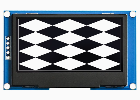
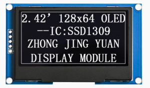
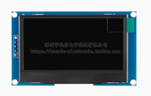
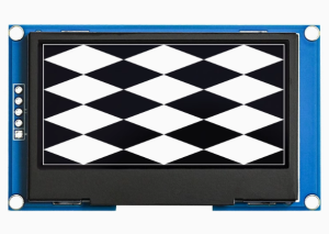
The 2.42-inch Passive Matrix OLED Display Module is a large-format, high-contrast monochrome graphic display designed for embedded systems, industrial control panels, medical devices, and IoT applications . Powered by the SSD1309 driver IC and featuring a crisp 128×64 pixel resolution, this display delivers bright white text, detailed graphics, and custom icons on a true black background — all in a spacious 2.42-inch diagonal format (approximately 61.5mm diagonal) .

Why the SSD1309 Controller?

Unlike the common SSD1306 controller used on smaller 0.96″ and 1.3″ OLEDs, the SSD1309 is specifically designed for larger OLED panels. It offers:

  • Higher row drive current: 40mA maximum vs. 15mA for SSD1306, providing brighter and more uniform illumination across the larger screen area

  • External boost regulator: These modules use an external switching boost converter (visible as a small inductor and diode on the PCB) to generate the higher voltage (approx. 12.5V) needed for larger OLED panels, replacing the internal charge pump used by SSD1306 modules

The 5-pin I2C interface (GND, VCC, SCL, SDA, RES) requires only two data lines to connect to your microcontroller, preserving valuable I/O pins for other peripherals. A dedicated RES (reset) pin allows hardware initialization of the display for reliable startup and recovery .

This module is compatible with ESP32, ESP8266, STM32, Raspberry Pi, and other 3.3V/5V logic systems. The I2C lines are 5V tolerant, making it safe for direct connection to 5V Arduino boards .

Key Features

  • Large 2.42-Inch Active Area: 55.01 × 27.49mm display area — approximately 6 times larger than 0.96″ OLEDs, providing significantly more screen real estate for dashboards, data visualization, and UI elements

  • White Monochrome OLED: Bright white pixels on true black background provide exceptional contrast and a professional, clean appearance

  • SSD1309 Driver IC: Advanced controller specifically designed for larger OLED panels, featuring higher row drive current for superior brightness uniformity, 256-step contrast control, and internal SRAM buffer (128 × 64 bits)

  • 5-Pin I2C Interface: Pins GND, VCC, SCL, SDA, RES — requires only 2 data lines (SDA/SCL) with default address 0x3C, saving GPIO pins

  • Dedicated RESET Pin: Allows external hardware reset control for reliable display initialization and recovery

  • Wide Operating Temperature: Rated for -40°C to +85°C, suitable for industrial and outdoor applications

  • Dual Voltage Logic Compatibility: I2C lines are 5V tolerant; works with both 3.3V (ESP32/ESP8266) and 5V (Arduino) systems — VCC requires 3.3V only

  • Full Viewing Angle: >160° visibility ensures clear readouts from any angle without contrast shift

Technical Specifications

Parameter Operating Value
Display Type Passive Matrix OLED (PMOLED)
Driver IC SSD1309
Resolution 128 × 64 pixels
Display Color White
Active Area (W × H) 55.01 × 27.49 mm
Module Dimensions (W × H) 61.5 × 39.5 mm
Pixel Size (W × H) 0.43 × 0.43 mm
Pixel Pitch (W × H) 0.39 × 0.39 mm
Default I2C Address 0x3C (configurable to 0x3D)
Logic Supply Voltage (VCC) 3.3V only (do not use 5V)
Logic I/O Compatibility 3.3V logic, 5V tolerant for I2C lines
Current Draw (All pixels off) ~2mA
Current Draw (All pixels on) ~285-290mA peak
Operating Temperature -40°C to +85°C
Storage Temperature -40°C to +85°C
Interface I2C (5-pin: GND, VCC, SCL, SDA, RES)

Pinout & Connection Guide

The module features a 5-pin I2C interface. Pin order may vary between manufacturers — always verify the silkscreen on your specific module.

Pin Definitions (5-Pin)

Pin Label Function Description
1 GND Ground Connect to power supply ground
2 VCC Power Supply 3.3V DC power input — DO NOT USE 5V
3 SCL I2C Clock Line Connect to SCL pin of microcontroller (3.3V logic, 5V tolerant)
4 SDA I2C Data Line Connect to SDA pin of microcontroller (3.3V logic, 5V tolerant)
5 RES / RST Reset (active low) Hardware reset; connect to MCU GPIO or pull HIGH through 10kΩ resistor to VCC

⚠️ Power Supply Warning

The VCC pin requires 3.3V only. Do not apply 5V to VCC — this can damage the module. The I2C lines (SDA/SCL) are 5V tolerant and can be connected directly to 5V microcontrollers, but the power supply must be 3.3V .

RESET Pin Configuration

The RES pin is critical for reliable operation. The module requires a proper reset signal to initialize correctly :

  • Option 1 (Recommended): Connect RES to a microcontroller GPIO pin and drive it HIGH in your setup code

  • Option 2: Pull RES HIGH to VCC through a 10kΩ resistor

  • Option 3: Connect directly to VCC (less reliable for some modules)

I2C Address Configuration

DC Pin State I2C Address 8-bit Address
Low 0x3C 0x78
High 0x3D 0x7A

If your module has a DC pin, it controls the I2C address. For fixed 5-pin configurations, the address is typically preset to 0x3C.

Wiring to ESP32

text
OLED Module          →    ESP32
─────────────────────────────────────
VCC (3.3V)           →    3.3V
GND                  →    GND
SCL                  →    GPIO22 (SCL)
SDA                  →    GPIO21 (SDA)
RES                  →    GPIO4 (with 10kΩ pull-up to 3.3V optional)

Wiring to Arduino Uno (5V)

⚠️ VCC must be 3.3V do not use 5V; I2C lines are safe for direct connection .

text
OLED Module          →    Arduino Uno
─────────────────────────────────────
VCC (3.3V)           →    3.3V pin
GND                  →    GND
SCL                  →    A5 (SCL)
SDA                  →    A4 (SDA)
RES                  →    D9 (with 10kΩ pull-up to 3.3V)

Wiring to Raspberry Pi

text
OLED Module          →    Raspberry Pi
─────────────────────────────────────
VCC (3.3V)           →    Pin 1 (3.3V)
GND                  →    Pin 6 (GND)
SCL                  →    Pin 5 (GPIO 3 / SCL)
SDA                  →    Pin 3 (GPIO 2 / SDA)
RES                  →    GPIO 17 (with 10kΩ pull-up to 3.3V)

Usage Guide

⚠️ Power Supply Considerations

This 2.42″ OLED draws significantly more current than smaller OLEDs — up to approximately 285-290mA when fully lit . Ensure your power source (especially the 3.3V regulator) can deliver adequate current. The Arduino Uno’s 3.3V pin is not designed for high current; use an external 3.3V regulator for this display.

  • All pixels off (black screen): ~2mA

  • Typical usage (partial lit): ~20-50mA

  • Full screen white (worst case): ~285-290mA peak

I2C Address Verification

Run this I2C scanner to verify your display’s address before using it:

cpp
#include <Wire.h>

void setup() {
  Wire.begin();
  Serial.begin(9600);
  Serial.println("I2C Scanner");
}

void loop() {
  byte error, address;
  int nDevices = 0;
  
  for(address = 1; address < 127; address++) {
    Wire.beginTransmission(address);
    error = Wire.endTransmission();
    
    if(error == 0) {
      Serial.print("I2C device found at address 0x");
      if(address < 16) Serial.print("0");
      Serial.println(address, HEX);
      nDevices++;
    }
  }
  
  if(nDevices == 0) Serial.println("No I2C devices found");
  delay(5000);
}

The default address is typically 0x3C .

Software Setup (Arduino IDE)

Step 1: Install the U8g2 Library

The U8g2 library by Oliver Kraus is the most reliable for SSD1309 displays, offering excellent support, many font options, and proper handling of the display’s reset requirements .

  1. Open Arduino IDE → Sketch → Include Library → Manage Libraries

  2. Search for “U8g2” by Oliver Kraus

  3. Click Install

Step 2: Basic Test Sketch

This example uses the correct constructor for the 2.42″ SSD1309 display and includes proper RESET pin handling .

cpp
#include <Arduino.h>
#include <U8g2lib.h>
#include <Wire.h>

// Correct constructor for 2.42" 128x64 SSD1309 over I2C
// The "F" (full buffer) variant updates faster but uses more RAM
// Parameter: reset pin number (use U8X8_PIN_NONE if not connected)
U8G2_SSD1309_128X64_NONAME0_F_HW_I2C u8g2(U8G2_R0, /* reset=*/ 4);  // GPIO4 for RES

void setup() {
  // If RES is connected to a GPIO, ensure it is pulled HIGH
  pinMode(4, OUTPUT);
  digitalWrite(4, HIGH);
  
  // Initialize the display
  u8g2.begin();
  u8g2.enableUTF8Print();
  u8g2.setFont(u8g2_font_ncenB08_tr);
  
  // Optional: Set I2C address if not default
  // u8g2.setI2CAddress(0x78);  // For address 0x3C
}

void loop() {
  u8g2.firstPage();                      // Start page loop
  do {
    u8g2.drawStr(0, 15, "2.42 OLED");
    u8g2.drawStr(0, 35, "128x64");
    u8g2.drawStr(0, 55, "SSD1309 - I2C");
    u8g2.drawStr(0, 75, "White Display");
  } while ( u8g2.nextPage() );           // Transfer buffer to display
  
  delay(1000);
}

Step 3: Setting I2C Address (If Needed)

If your display responds to address 0x3D instead of 0x3C, adjust the address in code :

cpp
// In setup(), before u8g2.begin()
u8g2.setI2CAddress(0x7A);  // For 7-bit address 0x3D (0x7A is 8-bit)

Adafruit Library Alternative

If you prefer the Adafruit library, note that the SSD1306 library is command-compatible with SSD1309, but you may need to adjust the display size :

cpp
#include <Wire.h>
#include <Adafruit_GFX.h>
#include <Adafruit_SSD1306.h>

#define SCREEN_WIDTH 128
#define SCREEN_HEIGHT 64
#define OLED_RESET -1   // Set to GPIO if RES connected

Adafruit_SSD1306 display(SCREEN_WIDTH, SCREEN_HEIGHT, &Wire, OLED_RESET);

void setup() {
  display.begin(SSD1306_SWITCHCAPVCC, 0x3C);
  display.clearDisplay();
  display.setTextSize(1);
  display.setTextColor(SSD1306_WHITE);
  display.setCursor(0, 0);
  display.println("2.42 OLED");
  display.println("SSD1309 Ready!");
  display.display();
}

Raspberry Pi Setup (Python)

  1. Enable I2C: sudo raspi-config → Interface Options → I2C → Yes → Reboot

  2. Install required libraries:

bash
sudo apt-get install python3-pip
pip3 install luma.oled
  1. Python example code:

python
from luma.core.interface.serial import i2c
from luma.oled.device import ssd1309
from luma.core.render import canvas

# I2C connection (address 0x3C, reset pin 17)
serial = i2c(port=1, address=0x3C, gpio_DC=18, gpio_RST=17)

device = ssd1309(serial, width=128, height=64)

with canvas(device) as draw:
    draw.rectangle(device.bounding_box, outline="white", fill="black")
    draw.text((10, 25), "2.42 OLED", fill="white")
    draw.text((10, 45), "128x64 Ready!", fill="white")
Q: What is the difference between SSD1309 and SSD1306?

The SSD1309 is designed specifically for larger OLED panels (2.42″ and up). Key differences: higher row drive current (40mA vs 15mA) for brighter, more uniform illumination; external boost regulator instead of internal charge pump; and command compatibility with SSD1306, making library migration straightforward .

Q: Why does my display stay blank after power-up unless I manually reset it?

The display requires a proper reset signal to initialize. Connect the RES pin to a microcontroller GPIO and pull it HIGH, or pull it HIGH to VCC through a 10kΩ resistor. Some modules require the RES pin to be toggled (HIGH → LOW → HIGH) during startup for reliable initialization .

Q: Can I use this display with a 5V Arduino Uno?

Yes, but with important caveats. The I2C lines (SDA/SCL) are 5V tolerant and can be connected directly to 5V pins. However, the VCC pin must be powered with 3.3V — do not apply 5V to VCC. The Arduino Uno’s onboard 3.3V regulator may not supply enough current (the display draws up to 290mA). Use an external 3.3V regulator for reliable operation .

Q: What is the default I2C address?

The default I2C address is 0x3C (7-bit), corresponding to 0x78 (8-bit write address). Some modules can be configured to 0x3D (0x7A) via the DC pin state . Run an I2C scanner to verify your specific module’s address.

Q: Why does the 2.42" display draw so much more current than smaller OLEDs?

The 2.42″ display has approximately 6 times the active area of 0.96″ displays. It requires more power to illuminate the larger panel. Peak current when all pixels are lit can reach approximately 290mA, compared to ~20mA for a 0.96″ display .

Q: Can I use this display with the Adafruit SSD1306 library?

Yes, the SSD1306 library is command-compatible with the SSD1309 and works with the 2.42″ display . However, the U8g2 library is generally better tested for this specific IC and provides more reliable results, especially for reset handling .

Q: Why is my I2C communication failing at higher speeds?

The larger display panel and PCB layout may add capacitance to the I2C bus. Try reducing the I2C clock speed to 100kHz or 400kHz for more reliable communication .

Q: Can I switch between I2C and SPI on this module?

The SSD1309 controller supports both interfaces, but this 5-pin module is factory-configured for I2C only. A 7-pin version would be needed for SPI communication .

Q: What is the lifespan of this OLED display?

OLEDs typically have a rated lifespan of approximately 50,000 hours of continuous operation (about 5.7 years). Avoid displaying static images for extremely long periods to prevent uneven pixel wear (“burn-in”) .

Q: Do I need external pull-up resistors for I2C?

Most SSD1309 modules include onboard 4.7kΩ pull-up resistors on the I2C lines . If you experience communication issues, adding external 4.7kΩ pull-ups may help, especially with longer wiring.