Product Overview
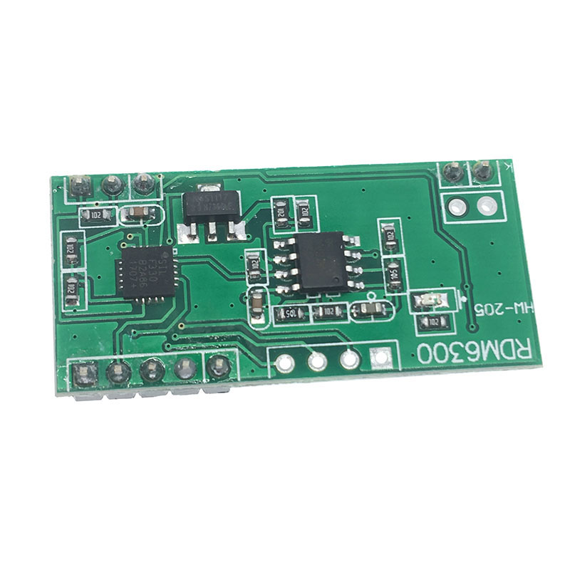
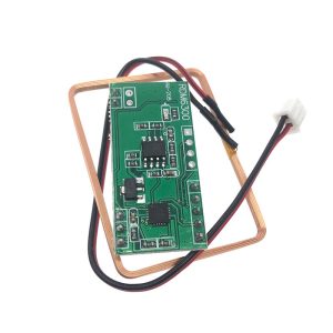
The RDM6300 125kHz RFID Card ID Reader Module is a compact, low-power radio frequency identification module designed to read EM4100-compatible passive RFID cards and tags . Operating at 125kHz, this module serves as a cost-effective solution for integrating RFID functionality into embedded systems, access control devices, and automation projects.
Unlike more complex RFID systems, the RDM6300 simplifies integration with its UART (TTL) serial interface. When an RFID card enters the module’s electromagnetic field, the reader decodes the unique 10-digit ID number and automatically transmits it via the serial port , requiring minimal processing overhead from your host microcontroller.
The module is designed for applications where reliable short-range reading and low power consumption are priorities. It is suited for access control systems, attendance tracking, consumer automation, and any project requiring identification of users or tagged objects.
Key advantages include plug-and-play functionality, compatibility with standard 5V microcontrollers like Arduino, and a proven track record among electronics hobbyists and professionals .
Key Features
-
125kHz Operating Frequency: Works with common EM4100 and EM4102 compatible RFID cards, key fobs, and stickers .
-
UART Serial Interface: Simple 4-pin connection (VCC, GND, TXD) transmits card ID data directly to your microcontroller .
-
EM4100 Protocol Support: Built-in decoding for the standard EM4100 series of read-only RFID tags.
-
9600 bps Fixed Baud Rate: Communicates at 9600 baud, 8 data bits, 1 stop bit, no parity (8N1) .
-
LED Indicator: Onboard LED provides visual confirmation when a tag is successfully read.
-
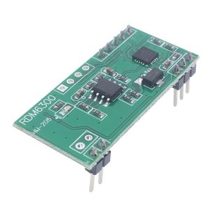
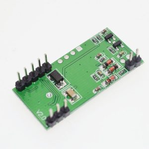
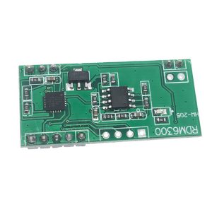
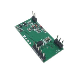
Compact Form Factor: Small PCB (approx. 38.5mm × 18.5mm) fits easily into enclosures and breadboard layouts .
-
5V Compatible: Operates on 5V DC and provides 0-5V TTL serial logic, making it compatible with 5V systems like Arduino Uno .
-
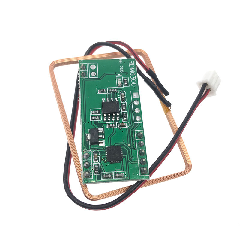
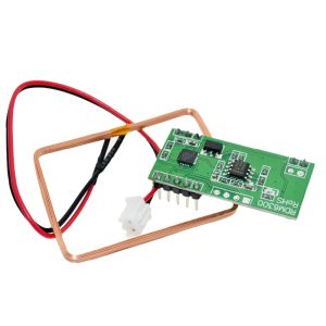
External Antenna Support: Includes screw terminals for connecting the included antenna coil.
Technical Specifications
Pinout & Connection Guide
Module Pin Descriptions
Note: The TXD pin transmits card data out from the module. This pin must connect to your microcontroller’s RX (receive) pin.
Wiring to Arduino Uno
RDM6300 Module          →    Arduino Uno
───────────────────────────────────────────
VCC                     →    5V
GND                     →    GND
TXD                     →    Digital Pin 3 (RX)
ANT1 / ANT2             →    Antenna Coil (non-polarized)
Data Output Format
When a valid RFID card enters the reader field, the module sends a data frame consisting of 14 bytes. The structure is as follows: Start Byte (02H) → 10-Byte Card ID (ASCII) → Checksum (XOR Byte) → Stop Byte (03H).
Example Output
Parsing the ID: The 10-byte ASCII sequence (e.g., “0102030405”) is the card’s unique identification number.
Usage Guide
Software Setup (Arduino)
The following example demonstrates how to read RFID card IDs from the RDM6300 using SoftwareSerial on an Arduino Uno.
#include <SoftwareSerial.h>
SoftwareSerial rfid(3, 4);
void setup() {
Serial.begin(9600);
rfid.begin(9600);
Serial.println("RDM6300 RFID Reader Ready");
}
void loop() {
if (rfid.available() >= 14) {
byte buffer[14];
for (int i = 0; i < 14; i++) {
buffer[i] = rfid.read();
}
if (buffer[0] == 0x02 && buffer[13] == 0x03) {
char cardID[11];
for (int i = 0; i < 10; i++) {
cardID[i] = buffer[i + 1];
}
cardID[10] = '\0';
Serial.print("Card ID: ");
Serial.println(cardID);
}
}
}
Explanation
-
Data Frame: The module sends a 14-byte packet whenever a valid tag is read.
-
Frame Validation: The sketch checks the start byte (0x02) and stop byte (0x03) .
-
ID Extraction: Bytes 2-11 contain the 10-digit card ID in ASCII format.
-
Action: Once verified, the ID can trigger an action (e.g., opening a door lock, logging attendance) .
Reading Distance Tips
The effective reading distance depends on several factors:
-
Tag Quality: EM4100 key fobs generally read from 2-5cm.
-
Power Supply: Stable 5V power < 50mA ripple improves stability.
-
Antenna Mounting: The reader antenna should not be placed near large metal surfaces.
Q: What types of RFID tags are compatible?
The RDM6300 module was designed for EM4100, EM4102, or compatible 125kHz read-only tags. These are standard, low-cost RFID cards available as key fobs, credit-card sized cards, or stickers .
Q: What is the difference between RDM6300 and RDM630?
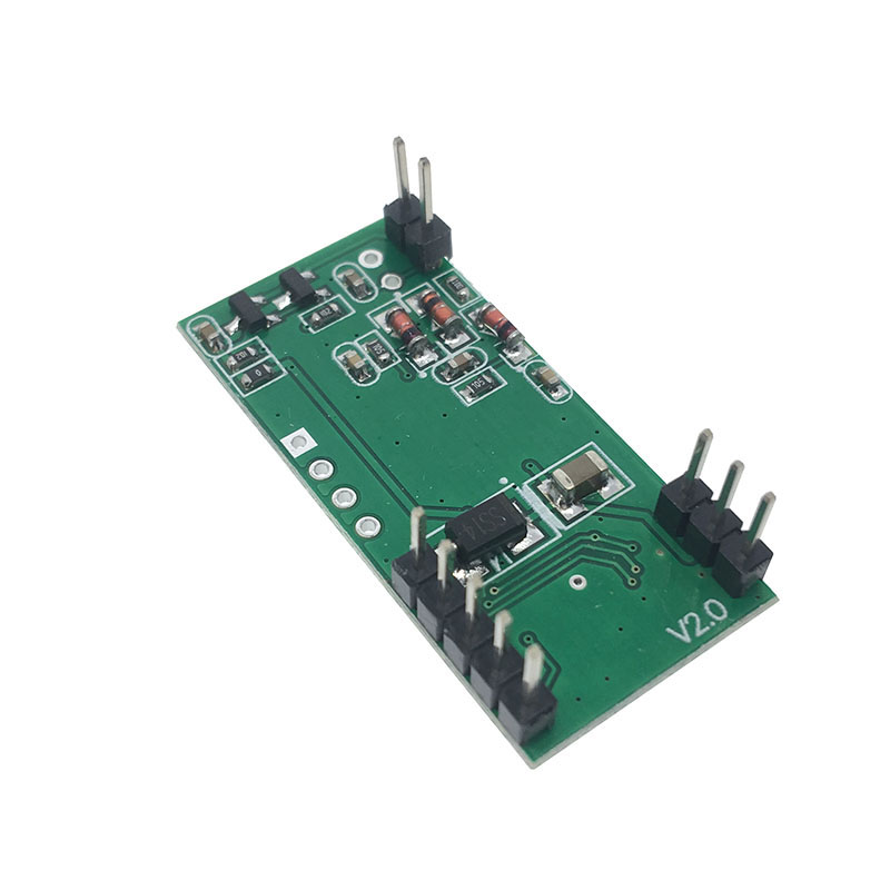
The RDM6300 is a more compact 6-pin module, while the classic RDM630 is larger and has a different antenna connector (JST- PH vs screw terminals). Both operate at 125kHz and use the same UART protocol. The RDM6300 is the recommended version for modern compact projects
Q: Can I read the card ID without an Arduino?
Yes, you can connect the TXD pin directly to a USB-to-TTL converter (5V). Using a computer serial terminal (e.g., PuTTY, CoolTerm) set to 9600 baud, you will see the raw card data appear when you tap an RFID card. This is a useful initial test to verify the module is functioning.
Q: Why is my module not reading any cards?
Check the following:
-
Connections are secure.
-
Antenna is firmly attached to the ANT1 and ANT2 terminals.
-
Power supply is stable at 5V.
-
In your code, verify that SoftwareSerial is initialized at 9600 baud.
-
Ensure your tag is EM4100 compatible.
-
Tap the card flat against the antenna coil.
Q: Can I use a 3.3V microcontroller (ESP32) with this 5V module?
Yes, but with caution. Power the RDM6300 from 5V (the ESP32 5V pin can source this). However, the RDM6300 TXD pin outputs 5V logic. You must use a logic level converter, a resistor divider (2kΩ and 3.3kΩ), or check if your ESP32 pin is 5V tolerant. Do not connect 5V logic directly to 3.3V pins.
Q: Does the module require an external power supply?
You can power it from a microcontroller’s 5V pin as long as your power source provides enough current (< 50mA). However, for access control systems or relay modules sharing the same power line, a dedicated 5V supply (wall adapter) is recommended to avoid brown-outs during relay activation.
Q: Can I use this module with a Raspberry Pi?
Yes. Connect the module’s 5V pin to a 5V GPIO pin on the Raspberry Pi (e.g., Pin 2, 5V). Connect TXD to an available UART RX pin (e.g., GPIO 15). Disable the Raspberry Pi’s serial console over GPIO in raspi-config to use the port freely .
Q: How can I extend the reading distance?
The factory range is 3-5 cm. Modifying the antenna is difficult and requires calibration with an oscilloscope and high-voltage COG/NPO capacitors . For longer range requiring 10cm+, an external active amplifier or a high-frequency (13.56MHz) reader is recommended.
Q: Why does the serial port show continuous garbage data?
This usually indicates a baud rate mismatch (default is 9600). Alternatively, you may have misconnected the TXD pin to the microcontroller’s TX pin (should be connected to RX) or your ground lines are not common.
Q: Can I write data to RFID tags with this module?
No. The RDM6300 is a read-only reader designed for EM4100 tags, which are passive, factory-programmed chips. You cannot encode or rewrite data to these cards. For read/write functionality, consider 13.56MHz modules like the PN532 or RC522.