Product Overview
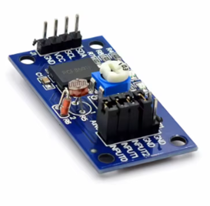
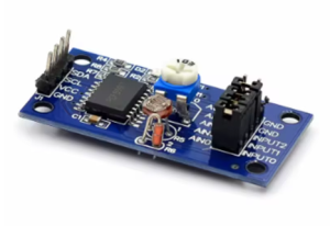
The PCF8591 AD/DA Converter Module (Big Board) is a versatile, low-power 8-bit data acquisition board designed to add analog input and analog output capabilities to any development system. Based on the NXP PCF8591 chip, this larger-format module serves as an essential interface between analog sensors and digital microcontrollers like Arduino, ESP32, or Raspberry Pi, which often lack built-in analog-to-digital converters .
The module provides 4 analog inputs (for reading sensors such as potentiometers, photoresistors, and temperature sensors) and 1 analog output (for controlling devices like LED brightness or small DC motors). Communication occurs via the simple 2-wire I2C bus, requiring only two pins (SDA and SCL) — making it an efficient solution for expanding your project’s sensing and control capabilities without consuming valuable GPIO resources .
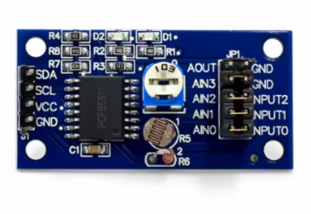
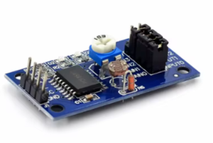
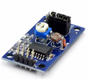
What distinguishes this “Big Board” version is its larger PCB design (approximately 36mm × 23mm) and extended functionality. The board integrates useful on-board components that enhance its versatility for learning and prototyping. It includes:
-
Built-in Photoresistor: For measuring ambient light intensity via AD acquisition.
-
Built-in Thermistor: For measuring ambient temperature via AD acquisition.
-
1-Channel 0-5V Voltage Input Acquisition: Controlled by an on-board blue potentiometer for adjustable voltage input.
-
DA Output Indicator LED: Lights up when the analog output reaches a certain threshold; brightness increases with higher output voltage .
Whether you need to read light sensors, monitor temperature, generate analog control signals, or teach the fundamentals of data acquisition, this PCF8591 module delivers a complete and cost-effective solution.
Key Features
-
4-Channel Analog Input (ADC): 4 configurable 0-5V analog input channels (AIN0–AIN3) for reading sensors, with built-in examples including a photoresistor (LED), thermistor, and voltage adjustment via potentiometer .
-
1-Channel Analog Output (DAC): 1 analog output (AOUT) for controlling dimmable devices; includes an on-board indicator LED that visualizes the output level .
-
8-Bit Resolution: Both the ADC and DAC offer 8-bit resolution (values from 0 to 255), providing 256 steps of precision .
-
I2C Interface: Simple 2-wire communication (SDA, SCL) uses only two pins, saving valuable microcontroller resources .
-
Multiple Address Support: Three hardware address pins (A0, A1, A2) allow up to 8 modules on the same I2C bus (address range 0x48–0x4f) .
-
Wide Voltage Support: Operates from 2.5V to 6V DC, compatible with both 3.3V (ESP32, Raspberry Pi) and 5V (Arduino) logic systems .
-
Built-in On-Board Components: Integrates a photoresistor, thermistor, and adjustable potentiometer for learning and prototyping without extra sensors.
-
Compact & Mountable: Board dimensions approximately 36mm × 23mm with 3mm mounting holes for easy installation .
Technical Specifications
Pinout & Connection Guide
Module Pin Definitions
The module provides pin headers on both sides for flexible connection. The labeling may vary slightly between manufacturers, so always verify the silkscreen on your specific board .
Right Side (Control Interface)
Left Side (Analog I/O)
Wiring Diagrams
Arduino Uno
Raspberry Pi / ESP32
Usage Guide
On-Board Jumper Configuration
The Big Board version includes red jumper caps that connect the on-board components to the analog input channels :
-
P4 Jumper: Connect to enable thermistor on AIN1.
-
P5 Jumper: Connect to enable photoresistor on AIN0.
-
P6 Jumper: Connect to enable potentiometer (0-5V adjustable) on AIN2.
Software Setup (Arduino IDE)
Install the “PCF8591” library by Rob Tillaart via the Library Manager .
Basic Arduino Test Code – Read All 4 Analog Inputs
#include <Wire.h>
#include "PCF8591.h"
PCF8591 adc;
void setup() {
Serial.begin(9600);
Wire.begin();
adc.begin(0x48);
adc.enableDAC();
Serial.println("PCF8591 Ready");
}
void loop() {
uint8_t val0 = adc.analogRead(0);
uint8_t val1 = adc.analogRead(1);
uint8_t val2 = adc.analogRead(2);
uint8_t val3 = adc.analogRead(3);
Serial.print("AIN0: "); Serial.print(val0);
Serial.print(" | AIN1: "); Serial.print(val1);
Serial.print(" | AIN2: "); Serial.print(val2);
Serial.print(" | AIN3: "); Serial.println(val3);
delay(500);
}
Raspberry Pi Setup (Python)
-
Enable I2C: sudo raspi-config → Interface Options → I2C → Enable → Reboot
-
Install smbus: sudo apt-get install python3-smbus
-
Example Python Code:
import smbus
import time
bus = smbus.SMBus(1)
address = 0x48
def read_ain(channel):
bus.write_byte(address, 0x40 | channel)
bus.read_byte(address)
return bus.read_byte(address)
while True:
for ch in range(4):
value = read_ain(ch)
print(f"AIN{ch}: {value:3d}", end=" ")
print()
time.sleep(0.5)
Q: Why do I need this PCF8591 module for my Raspberry Pi?
The Raspberry Pi does not have built-in analog-to-digital converters (ADC), meaning it cannot directly read analog sensors. The PCF8591 module provides 4 analog input channels to solve this problem . Additionally, it provides a DAC output for generating analog voltages.
Q: Can I connect more than one PCF8591 module to the same I2C bus?
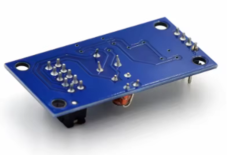
Yes. The PCF8591 chip has three hardware address pins (A0, A1, A2) that allow you to set up to 8 different addresses (0x48 to 0x4f) . By soldering the address jumpers on the back of the module, you can connect multiple boards to the same I2C bus.
Q: How many analog inputs does this module provide?
The PCF8591 provides 4 analog inputs (AIN0–AIN3). However, these inputs are multiplexed internally, meaning the ADC reads them sequentially. The chip can be configured to auto-increment the channel selection after each read .
Q: What is the difference between the "Big Board" and "Small Board" versions?
The Big Board version (this product) has a larger PCB footprint and includes on-board components: a photoresistor (for light sensing), a thermistor (for temperature sensing), and a potentiometer (for adjustable voltage input). The small board version typically lacks these built-in components and is more compact .
Q: What is the maximum voltage I can apply to the analog inputs?
The analog input voltage range is from 0V to VCC (the voltage you supply to the module). To avoid damage, do not exceed VCC (e.g., if powered at 5V, inputs should be within 0–5V).
Q: How accurate is the 8-bit conversion?
With 8-bit resolution, the ADC divides the input voltage range (e.g., 0–5V) into 256 steps (0 to 255). This provides approximately 19.5mV per step (5V ÷ 256). For many hobbyist applications (reading potentiometers, photocells, temperature sensors), this is sufficient. For higher precision applications, consider a 10-bit or 12-bit ADC module.
Q: Can I use 3.3V logic (Raspberry Pi, ESP32) with this 5V module?
Yes. For Raspberry Pi and ESP32, the recommended approach is to power the module with 3.3V (connect VCC to 3.3V instead of 5V). This ensures logic levels are compatible .
Q: Does this module require external pull-up resistors for I2C?
The PCF8591 module typically includes onboard pull-up resistors for the I2C lines. However, if you are using long wires or multiple I2C devices, you may need to add external 4.7kΩ pull-ups.
Q: What are the four analog input modes for?
The different input modes allow you to configure the ADC for :
-
Mode 0 (Default) : Four single-ended inputs — each input voltage measured relative to ground. Best for connecting multiple independent sensors.
-
Mode 1: Three differential inputs (one shared reference).
-
Mode 2: Mixed single-ended and differential.
-
Mode 3: Two differential inputs.
Q: What is included in this package?
The package includes:
-
1 x PCF8591 AD/DA Converter Module (Big Board with on-board photoresistor, thermistor, potentiometer)
-
No jumper cables included (sold separately)