Product Overview
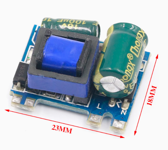
The 5V 600mA Switching Power Supply Module is a compact, high-efficiency AC-DC converter designed to power your microcontroller projects, IoT devices, and embedded systems directly from a wall outlet. Rated at 3.5 Watts (5V @ 600mA), this tiny module eliminates the need for bulky power bricks by converting hazardous AC mains voltage (85V–265V) into a stable, regulated 5V DC output.
This encapsulated switching power supply is a perfect solution for powering Arduino, ESP32, STM32, relay modules, LED strips, and sensor networks. Unlike traditional linear transformers that are heavy and inefficient, this switching mode power supply (SMPS) achieves up to 74% efficiency while staying cool, thanks to its modern flyback topology .
Because the module uses a high-frequency transformer and complies with international safety standards, it provides complete electrical isolation between the dangerous high-voltage AC input and the low-voltage DC output. This ensures the safety of both your sensitive electronics and the person handling the equipment .
Its fully encapsulated plastic case protects against dust, moisture, and accidental contact, making it ideal for integration into home appliances, automation panels, and commercial electronics .
Key Features
-
PCB Mount Design: Fully encapsulated plastic case can be soldered directly onto a printed circuit board (PCB), making it ideal for high-volume production and permanent installations .
-
Universal AC Input: Accepts a wide input voltage of 85V to 264V AC (or 90-264V depending on the exact variant), making it compatible with mains power worldwide (110V, 220V, 240V) without any jumpers.
-
Efficient Switching Topology: Features high efficiency (up to 74%) and low heat generation, minimizing energy waste and ensuring long-term reliability in enclosed spaces .
-
Sufficient 600mA Capacity: Provides a steady 5V output with 600mA continuous current, capable of powering most low-power microcontrollers, wireless modules (ESP8266), and sensors simultaneously.
-
Protected and Safe: Built-in overcurrent, short-circuit, and overload protections prevent damage to the module and your downstream devices during fault conditions .
-
Low Output Ripple: Despite being a switching supply, it maintains low output ripple and noise, ensuring stable operation for sensitive analog circuits .
-
Wide Operating Temperature: Rated for an ambient temperature range of -25°C to +60°C, suitable for a variety of indoor and light-industrial environments .
-
Easy DIY Wiring: The module features standard through-hole pins (2.54mm pitch) for easy soldering to a PCB or for connecting wires manually using female jumper cables .
Technical Specifications
Pinout & Connection Guide
The module uses a standard pin arrangement for easy breadboard or PCB wiring. The pins are typically spaced at 2.54mm. Always verify the specific labeling on your module before connecting power.
AC Input Side (Primary Side)
-
L (Live/Line):
Connect to the “Hot” wire of the AC mains outlet (usually Black or Brown wire). It is recommended to add a fuse (e.g., 1A slow-blow) and a physical on/off switch in line with this wire for safety.
-
N (Neutral):
Connect to the Neutral return wire of the AC mains outlet (usually White or Blue wire).
DC Output Side (Secondary Side)
-
+5V (Vout):
Connect to the positive power rail of your Arduino (e.g., 5V pin), ESP32, or other DC load.
-
GND (Common):
Connect to the ground (GND) of your microcontroller and the return path of your load.
Wiring Warning: Ensure the AC wiring is properly insulated and kept physically separated from the DC output side to maintain isolation and prevent short circuits. Always connect AC power through a switch and fuse for permanent installations.
Usage Guide
Safety First (Critical)
⚠️ This module deals with potentially lethal high voltage. Always ensure the device is UNPLUGGED during wiring. Do not touch any part of the AC side or the underside pins while the device is powered.
Step 1: Mounting
-
For Prototyping: Solder female pin headers to the 4 main pins. You can then plug it into a breadboard or connect jumper wires.
-
For Permanent Installation: Solder the module directly to your custom PCB using the 4 through-hole pins .
Step 2: Connect AC Input
Step 3: Connect DC Load
Step 4: Power On
-
Double-check all connections for shorts.
-
Plug the module into a standard AC outlet (110V or 220V).
-
Use a multimeter to verify the output voltage is 5V (±5%) before connecting expensive components.
Application Note
Because this module operates at a high switching frequency, it may introduce high-frequency noise into the DC output. For powering sensitive analog circuits (like audio preamps or high-resolution ADCs), consider adding a low-ESR filter capacitor (e.g., 100µF or 470µF electrolytic in parallel with a 0.1µF ceramic) across the 5V and GND output terminals to reduce ripple further.
Q: Can I use this module to power an Arduino Uno or Nano directly?
Yes. You can, but not via the Barrel Jack. Connect the module’s 5V output directly to the Arduino’s 5V pin and the GND to GND. Do not connect 5V to the VIN pin, as that bypasses the voltage regulator and could damage the board. This method is perfect for permanent, wall-powered installations.
Q: How many devices can I power with 600mA?
600mA is enough for an Arduino board (approx. 80-150mA), a couple of LED indicators (20mA each), and a basic sensor (e.g., DHT11 or HC-SR04). It is generally sufficient for non-motorized, low-power projects. If you plan to run high-power devices like servos, relays, or large LED strips, you will need a higher current power supply.
Q: Is this module isolated? Is it safe to touch the output wires while powered?
Yes and Yes. This module uses a high-frequency transformer to provide galvanic isolation between the input AC mains and the output DC voltage. Because they are separated, touching the 5V output wires is safe (although you should never touch the AC input side).
Q: The specification says 600mA, but it is labeled 3.5W. Does that match?
Yes, perfectly. Power (Watts) = Volts (5V) × Current (Amps). 5V × 0.6A = 3.0 Watts. However, the module is rated as a 3.5W system because the charger has a safety margin (derating) and an efficiency of 72%, meaning it can draw up to 3.8W from the wall to output the 3W your device uses
Q: What is the difference between this switching power supply and a standard phone charger?
Both are AC-DC converters. However, this is a bare-board PCB module designed to be soldered directly into your project. Phone chargers come in a plastic case with a USB port. This module is smaller and integrates directly into your hardware, whereas a phone charger is an external accessory.
Q: Can I use this module to charge a lithium battery?
No, not directly. This is a Constant Voltage (CV) power supply. A lithium battery requires a Constant Current/Constant Voltage (CC/CV) charging profile. Using this directly could over-current and damage the battery. You must use a dedicated TP4056 or similar charging module between this power supply and your battery.
Q: The module gets warm. Is this normal?
Yes. At near-maximum load (600mA), the module will generate some heat due to the 26% inefficiency (resulting in about 1 Watt of heat). This is normal for a 3.5W encapsulated power supply. However, if it is too hot to touch, ensure there is adequate airflow and that you are not exceeding the 600mA limit.
Q: Can I use a 12V DC input to power this "AC-DC" module?
No, not at all. This module is designed specifically for AC Mains voltage. The internal high-frequency transformer expects a rectified high voltage (approx. 120V-350V DC) derived from AC. Applying 12V DC will not be enough to start the control IC, and the module will not function.
Q: Can I solder the wires directly to the pins, or do I need a connector?
You can solder wires directly to the through-hole pins. This is the most common and reliable method for permanent installations. For prototyping, soldering a 4-pin male header makes it easy to plug into a breadboard.
Q: Does this module require external components to work?
It is a standalone power supply. It does not require any external capacitors or resistors to provide a stable 5V output. You simply connect the AC input and DC output, and it works. Adding a fuse and switch on the AC line is recommended for safety, but not required for basic operation.