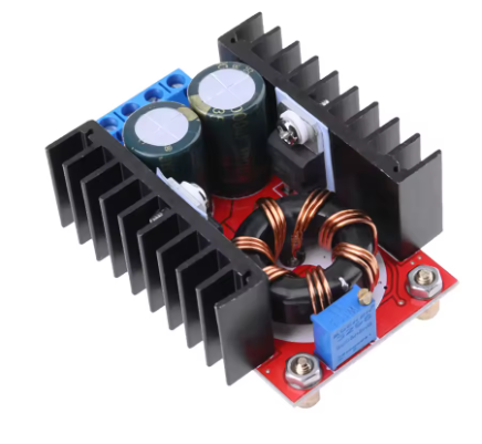
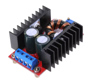
Product Overview
The 150W Boost Converter DC-DC Step-Up Module is a high-performance adjustable voltage regulator designed to step up a lower DC input voltage (10-32V) to a higher, user-adjustable DC output voltage (12-35V) . This powerful module can deliver up to 150W of output power and support currents up to 6A-10A, making it an essential tool for electronics enthusiasts, automotive applications, and industrial projects.
This boost converter module is based on a high-efficiency switching regulator design (often utilizing UC3844, XL, or TPS series ICs), which allows it to achieve conversion efficiencies of up to 94% . The result is less energy wasted as heat and more power delivered to your load, all within a compact, heatsink-equipped package.
Whether you need to power a 19V laptop from a 12V car battery, charge a 24V battery bank from a 12V solar panel, or run 24V-35V DC motors in a robotics project, this versatile step-up converter provides a reliable and adjustable solution. The output voltage is continuously adjustable via an onboard precision multi-turn potentiometer, allowing you to dial in exactly the voltage your application requires .
Key Features
-
Wide Input Voltage Range: Accepts DC inputs from 10V to 32V, making it compatible with 12V lead-acid batteries, 24V industrial supplies, solar panels, and various DC adapters .
-
Adjustable High-Voltage Output: Provides a continuously adjustable output from 12V to 35V DC via a multi-turn potentiometer, covering common voltages like 13.8V, 19V, 24V, and 28V .
-
High Power Output: Capable of delivering up to 150W maximum output power (100W with natural cooling, 150W with enhanced active cooling) . Supports up to 6A continuous output current .
-
High Efficiency: Achieves up to 94% conversion efficiency (measured at 16V input, 19V output, 2.5A), minimizing power loss and heat generation .
-
Industrial Temperature Range: Rated for operation from -40°C to +85°C, suitable for demanding environments .
-
Built-in Heatsink: Pre-installed aluminum heatsink on the main switching components provides effective passive cooling for up to 100W loads .
-
Onboard Status LED: Power indicator LED illuminates when input voltage is applied, confirming the module is active .
-
Screw Terminal Connections: Large, reliable screw terminals for secure input and output wiring, rated for the required current .
-
Compact, Non-Isolated Design: Small footprint (approx. 65x35x20mm) allows for easy integration into projects and enclosures .
Technical Specifications
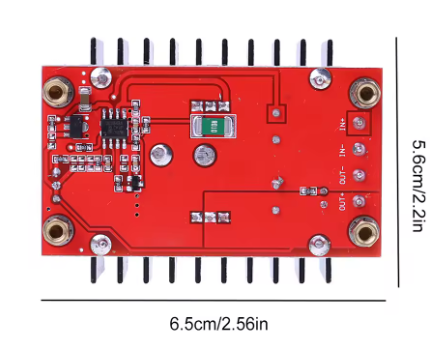
Pinout & Connection Guide
The module features clearly labeled screw terminals for all input and output connections .
Input Terminals (Power Source)
Output Terminals (Load Connection)
User Adjustments
Critical Safety Warning:
-
No Short Circuit Protection: This module does NOT have short circuit protection. You should install a fuse (15A-20A) on the input side.
-
No Reverse Polarity Protection: Connecting the input power with reversed polarity will instantly destroy the module. Always double-check your wiring before applying power.
-
Output Must be Higher than Input: This is a BOOST (step-up) converter only. The output voltage must always be higher than the input voltage.
Usage Guide
Important Safety Warnings
⚠️ No Built-in Protections: This module does NOT include short circuit protection or reverse polarity protection. You MUST install external protection circuits :
-
Add a 15A-20A fuse in series with the input to prevent catastrophic failure during overloads.
-
Add a high-current Schottky diode in series with the input to protect against reverse polarity.
-
Failure to add these protections may result in damage to the module, fire, or personal injury.
⚠️ Use a Multimeter: The factory default output voltage is often set to a dangerously high level (~22V) . Always measure and adjust the output voltage BEFORE connecting your load to prevent damage to your equipment.
Wiring Instructions
IMPORTANT: Disconnect input power before wiring or modifying connections.
Step 1 – Add External Protection (Recommended)
-
For Overload Protection: Connect a 15A-20A fast-blow fuse in series with the input positive wire.
-
For Reverse Polarity Protection: Connect a high-current Schottky diode (e.g., 20SQ045) in series with the input positive wire. The cathode (banded end) should point towards the module’s IN+ terminal.
Step 2 – Wiring
-
Connect Input: Connect the positive wire of your DC power source (10-32V) to the IN+ terminal. Connect the negative wire to the IN- terminal.
-
Connect Output: Connect your device/load to the OUT+ and OUT- terminals.
-
Set Initial Voltage: Before applying power to your load, turn the potentiometer fully counter-clockwise (minimum voltage).
-
Power & Adjust: Apply input power. Place a multimeter on the output terminals. Slowly turn the potentiometer clockwise until you reach your desired output voltage (e.g., 19V for a laptop) .
-
Connect Load: Turn off input power, connect your load to the output terminals, and re-apply power.
Calibration Procedure
-
Apply the intended input voltage (e.g., 12V from a battery) and set a moderate load (e.g., 1A). Measure the output voltage with a multimeter.
-
Adjust the potentiometer while monitoring the output voltage to achieve the setpoint needed for your device.
Typical Applications
Power Derating & Thermal Management
The maximum output power depends heavily on cooling :
At full load (150W), the module temperature will rise approximately 45°C above ambient. For a 25°C room, expect the module to reach around 70°C—this is normal, but a fan is highly recommended .
Q: Why does the output voltage drop when the load increases?
This is typically due to wire resistance or an undersized power supply. Measure the voltage at the module’s input terminals under load. If it drops significantly, your source or wires cannot deliver the required current. Additionally, ensure you are not exceeding the 150W power limit .
Q: Why does my connected device (e.g., laptop) not start or charge?
A common reason is insufficient peak current delivery. Some devices, like laptops, require high inrush current at startup. The module may current-limit, causing the voltage to drop. Solutions include: Add a large capacitor (2000-5000µF) across the output, upgrade input wiring, or use a higher-current power supply .
Q: What is the efficiency of this converter?
Efficiency can reach as high as 94% under optimal conditions (e.g., 16V input to 19V output at moderate load) . Efficiency is lowest when the difference between input and output voltage is very large (e.g., 10V in to 35V out) or at very light loads.
Q: Does this module have short circuit or reverse polarity protection?
NO. This module lacks both protections. You MUST install an external fuse (for shorts) and a series diode (for reverse polarity) at the input. Failure to do so can result in permanent damage to the module, fire, or injury.
Q: What is the default output voltage from the factory?
The factory setting is often set to a random high voltage, typically around 20V-22V . Always use a multimeter to set the correct voltage BEFORE connecting your load.
Q: Why does the no-load current read 25mA?
The control circuitry inside the boost converter draws a small amount of power even when nothing is connected to the output. This is normal for a switching regulator. It allows for fast load response and maintains output voltage stability .
Q: Can I use this to charge a battery (e.g., 24V lithium pack from 12V)?
Yes, but with caution. This is a constant voltage (CV) power supply. For battery charging, you need a constant current/constant voltage (CC/CV) charger. You can use this as the front-end power supply, but you will need to add a constant current regulator or use a dedicated battery management system (BMS) between this module and the battery to ensure safe charging .
Q: Is the output isolated from the input?
No. This is a non-isolated BOOST converter. The input and output share a common ground. Do not use this module for applications that require galvanic isolation between the source and the load.
Q: Can I use this module to get a lower voltage than my input (buck function)?
No. This is a step-up (BOOST) converter only. The output voltage cannot be lower than the input voltage . To lower voltage, you need a separate Buck (step-down) converter.
Q: How do I get 150W output reliably?
To achieve 150W, you must:
-
Provide an input current of at least 12A (since power = V_in × I_in).
-
Install a fan for active cooling as natural cooling is insufficient above 100W .
-
Use a high-quality power source with low internal resistance and thick wires (at least 14 AWG).