Product Overview
The BMX055 9-Axis IMU Sensor Module is a high-performance motion tracking solution from Bosch Sensortec, designed as a compact and versatile alternative to the popular MPU9250. Combining a 3‑axis accelerometer, a 3‑axis gyroscope, and a 3‑axis geomagnetic sensor in a single LGA package (3.0 × 4.5 mm²), the BMX055 delivers true 9‑degree‑of‑freedom (9‑DOF) inertial measurement for a wide range of applications .
Unlike many IMUs that require separate chips for accelerometer/gyroscope and magnetometer, the BMX055 integrates all three sensing elements into one tiny component, significantly reducing board space and simplifying system design . It supports both I²C and SPI digital interfaces, operates from 2.4 V to 3.6 V, and features on-chip FIFO buffers, interrupt controllers, and temperature sensors for smart, low‑power operation .
The BMX055 is an excellent choice for drones, robotics, wearable devices, orientation tracking, gesture recognition, and any application requiring precise motion and heading detection. Its small footprint, programmable features, and Bosch’s proven MEMS technology make it a compelling option for designers seeking an alternative to the MPU9250.
Note: The BMX055 is officially designated as end of life (EOL) or obsolete by Bosch, but it remains widely available and is still actively used in many projects .
Key Features
-
Integrated 9‑Axis Sensor: Combines a 3‑axis accelerometer, 3‑axis gyroscope, and 3‑axis magnetometer in a single LGA‑20 package .
-
Wide Measurement Ranges:
-
Accelerometer: ±2g, ±4g, ±8g, ±16g (16‑bit output) .
-
Gyroscope: ±125°/s, ±250°/s, ±500°/s, ±1000°/s, ±2000°/s (16‑bit output) .
-
Magnetometer: ±1300 µT (X‑Y axes), ±2500 µT (Z‑axis) .
-
Digital Interfaces: Supports both I²C (up to 400 kHz) and SPI (4‑wire and 3‑wire) protocols for flexible microcontroller integration .
-
Low Power Consumption: Active current as low as 130 µA for the accelerometer, with fast wake‑up times (1.3 ms) and idle power‑saving modes .
-
On‑Chip FIFO Buffers: Integrated FIFOs (32 frames for accelerometer, 100 frames for gyroscope) reduce host processor load and enable low‑power data logging .
-
Programmable Interrupts: Motion‑triggered interrupt generation for new data, slope detection, tap sensing, orientation change, and inactivity recognition .
-
Wide Operating Voltage: VDD range 2.4 V – 3.6 V, VDDIO range 1.2 V – 3.6 V, allowing easy interfacing with both 3.3 V and 5 V systems (with level shifting) .
-
Industrial Temperature Range: Rated for -40°C to +85°C, suitable for demanding environments .
-
Compact LGA Package: Small footprint of 3.0 × 4.5 mm², height 0.95 mm, ideal for space‑constrained designs .
Technical Specifications
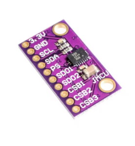
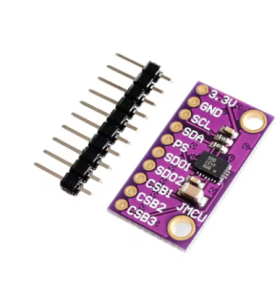
Pinout & Connection Guide
The BMX055 is housed in a 20‑pin LGA package. Key pins and their functions are summarized below. For the full pinout, refer to the official Bosch datasheet.
Interface Mode Selection
Wiring Diagram (I²C Mode – Recommended)
Note: The BMX055 operates at 3.3 V logic. For 5 V microcontrollers (e.g., Arduino Uno), use a logic level converter on SDA, SCL, and other signal lines to avoid damaging the sensor .
I²C Address Selection
Default Configuration: On most breakouts, SA0 is pulled to GND, so the default I²C address is 0x18.
Usage Guide
Software Setup (Arduino IDE)
Step 1: Install Required Libraries
The BMX055 is supported by several Arduino libraries. The most common are:
-
BMX055 Arduino Library by Bosch Sensortec (official)
-
BMX055 by Love Engineering
-
DFRobot BMX055 (compatible with DFRobot’s sensor ecosystem)
Install via Arduino Library Manager:
-
Open Arduino IDE → Sketch → Include Library → Manage Libraries.
-
Search for “BMX055”.
-
Install your preferred library.
Step 2: I²C Address Verification
Run this I²C scanner to verify your sensor’s address before writing code:
#include <Wire.h>

void setup() {
  Wire.begin();
  Serial.begin(9600);
  Serial.println("\nI2C Scanner");
}

void loop() {
  byte error, address;
  int nDevices = 0;

  for(address = 1; address < 127; address++) {
    Wire.beginTransmission(address);
    error = Wire.endTransmission();

    if(error == 0) {
      Serial.print("I2C device found at address 0x");
      if(address < 16) Serial.print("0");
      Serial.println(address, HEX);
      nDevices++;
    }
  }

  if(nDevices == 0) Serial.println("No I2C devices found");
  delay(5000);
}
Expected output: 0x18 (or 0x19 if SA0 is pulled HIGH).
Step 3: Basic Accelerometer Read Example
This example reads accelerometer data and prints it to the Serial Monitor .
BMX055 Basic Accelerometer Read Example
*/
#include <Wire.h>
#include <BMX055.h>
BMX055 bmx;
void setup() {
Serial.begin(9600);
Wire.begin();
bmx.beginAcc(0x3);
Serial.println("BMX055 Accelerometer Ready");
Serial.println("-----------------------------");
}
void loop() {
int xAcc = bmx.getAccelerationX();
int yAcc = bmx.getAccelerationY();
int zAcc = bmx.getAccelerationZ();
float ax = xAcc / 16384.0;
float ay = yAcc / 16384.0;
float az = zAcc / 16384.0;
Serial.print("Accel (g): ");
Serial.print(ax); Serial.print(", ");
Serial.print(ay); Serial.print(", ");
Serial.println(az);
delay(100);
}
Step 4: Complete 9‑Axis Read Example (Full IMU)
BMX055 Complete 9-Axis Read Example
Reads accelerometer, gyroscope, and magnetometer data
*/
#include <Wire.h>
#include <BMX055.h>
BMX055 bmx;
void setup() {
Serial.begin(115200);
Wire.begin();
bmx.begin();
Serial.println("BMX055 9-Axis Sensor Ready");
Serial.println("----------------------------------------");
}
void loop() {
float ax = bmx.getAccelX();
float ay = bmx.getAccelY();
float az = bmx.getAccelZ();
float gx = bmx.getGyroX();
float gy = bmx.getGyroY();
float gz = bmx.getGyroZ();
float mx = bmx.getMagX();
float my = bmx.getMagY();
float mz = bmx.getMagZ();
float heading = atan2(my, mx) * 180 / PI;
if (heading < 0) heading += 360;
Serial.print("Accel (g): ");
Serial.print(ax); Serial.print(", ");
Serial.print(ay); Serial.print(", ");
Serial.println(az);
Serial.print("Gyro (°/s): ");
Serial.print(gx); Serial.print(", ");
Serial.print(gy); Serial.print(", ");
Serial.println(gz);
Serial.print("Mag (µT): ");
Serial.print(mx); Serial.print(", ");
Serial.print(my); Serial.print(", ");
Serial.println(mz);
Serial.print("Heading: ");
Serial.print(heading);
Serial.println("°");
Serial.println("----------------------------------------");
delay(100);
}
Sensor Fusion and Magnetometer Calibration
The BMX055’s magnetometer is susceptible to hard‑iron and soft‑iron distortions from nearby magnetic materials (motors, wires, batteries). For accurate heading, calibration is essential .
Calibration Procedure:
-
Collect raw magnetometer data while rotating the sensor in a figure‑eight pattern.
-
Record the minimum and maximum values for each axis.
-
Calculate hard‑iron offsets: bias = (max + min) / 2.
-
Apply offsets to future readings: X_cal = X_raw – bias_X, etc.
-
Recalculate heading using calibrated values.
Some BMX055 libraries include built‑in magnetometer calibration functions.
Using SPI Instead of I²C
For higher data rates or when multiple IMUs share the same bus, SPI is preferred. SPI offers faster throughput (up to 10 MHz) and uses separate MISO/MOSI lines .
SPI Wiring:
SPI Initialization (Arduino):
BMX055 bmx(CS_PIN);
bmx.begin();
Q: What is the difference between BMX055 and MPU9250?
Both are 9‑axis IMUs, but they differ in specifications and performance . The MPU9250 generally offers better accelerometer noise performance and overall trajectory tracking accuracy. However, the BMX055 has a lower gyroscope zero‑rate offset (±1 deg/s) and a smaller package (3.0 × 4.5 mm²) . A 2017 study concluded that MPU9250 performed best overall, while BMX055 was the worst in pedestrian tracking tests . However, the BMX055 remains a capable, cost‑effective option for less demanding applications.
Q: Is the BMX055 still in production?
According to multiple sources, the BMX055 is end of life (EOL) or considered obsolete . However, it remains widely available through distributors and is still used in many active projects.
Q: What are the default I²C addresses of the BMX055?
The default 7‑bit I²C address is 0x18 when the SA0 pin is connected to GND, and 0x19 when SA0 is connected to VDDIO .
Q: Can I power the BMX055 directly from a 5 V Arduino?
No. The BMX055 operates at 3.3 V logic only. Applying 5 V directly to VDD or VDDIO may damage the sensor. You can use a 3.3 V regulator or, for I²C, you may be able to power VDD from 3.3 V while using level shifters on the SDA/SCL lines if your microcontroller runs at 5 V .
Q: What are the measurement ranges of the accelerometer and gyroscope?
Accelerometer: ±2g, ±4g, ±8g, ±16g . Gyroscope: ±125°/s, ±250°/s, ±500°/s, ±1000°/s, ±2000°/s .
Q: Does the BMX055 have an on‑chip FIFO buffer?
Yes. It has a 32‑frame FIFO for the accelerometer and a 100‑frame FIFO for the gyroscope, which reduces host processor load and enables low‑power data logging .
Q: Can I use this sensor with a Raspberry Pi?
Yes. The BMX055 communicates via I²C or SPI, both of which are supported on the Raspberry Pi. Enable I²C via raspi-config, connect the sensor to the 3.3 V pins, and use Python libraries such as bmx055 or adafruit-circuitpython-bmx055.
Q: What is the maximum output data rate (ODR) of the BMX055?
The maximum bandwidth for the accelerometer is 1 kHz, and the gyroscope bandwidth ranges from 12 Hz to 230 Hz, depending on the low‑pass filter settings .
Q: Does the BMX055 require calibration?
The magnetometer requires calibration to compensate for hard‑iron and soft‑iron distortions caused by nearby magnetic materials. The gyroscope and accelerometer are factory‑trimmed but may benefit from a simple offset calibration for best accuracy .
Q: What are the main applications of the BMX055?
The BMX055 is used in drones, robotics, wearable devices, orientation tracking systems, gesture recognition, heading references, and pedestrian navigation. Its compact size and low power consumption make it well‑suited for portable and battery‑powered applications .