


Description
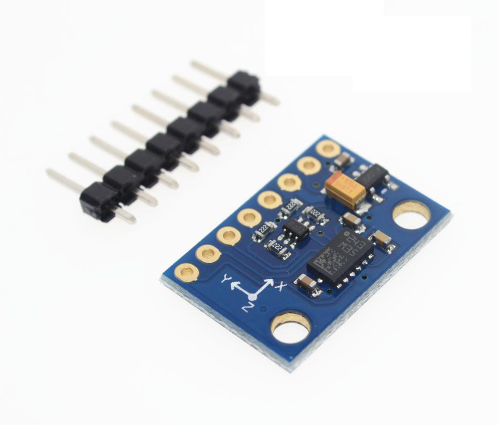
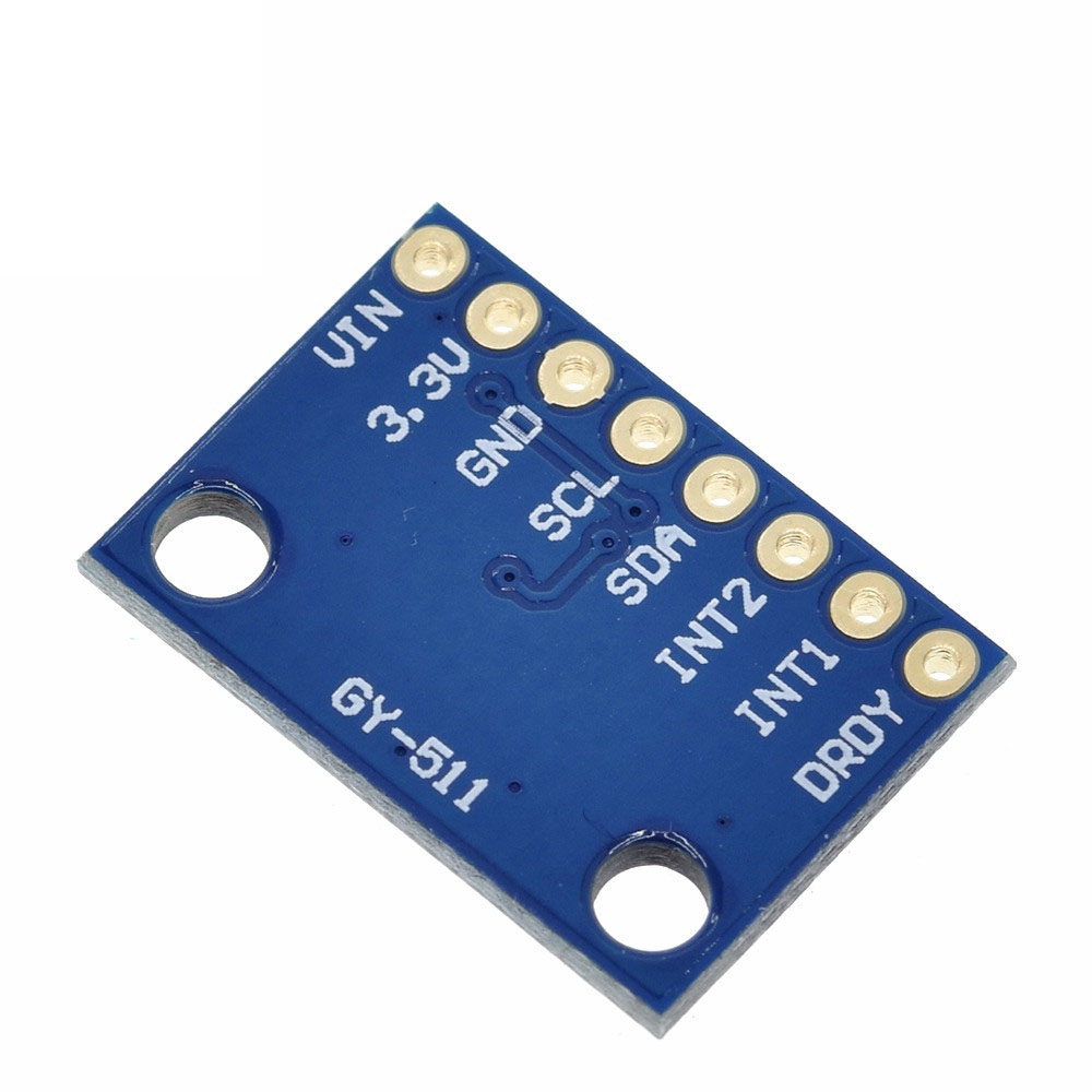
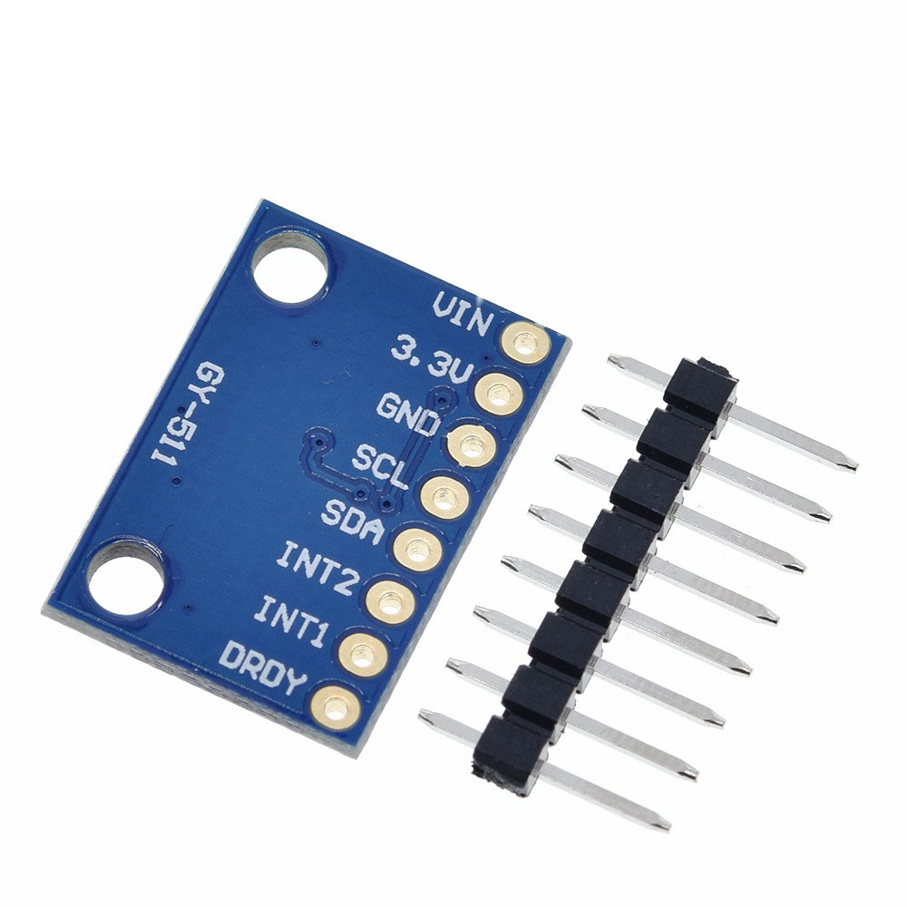
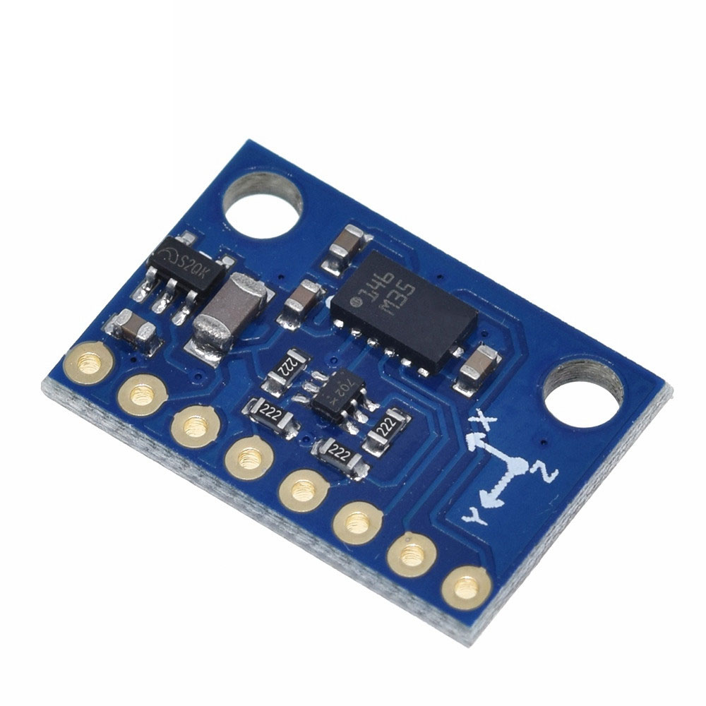
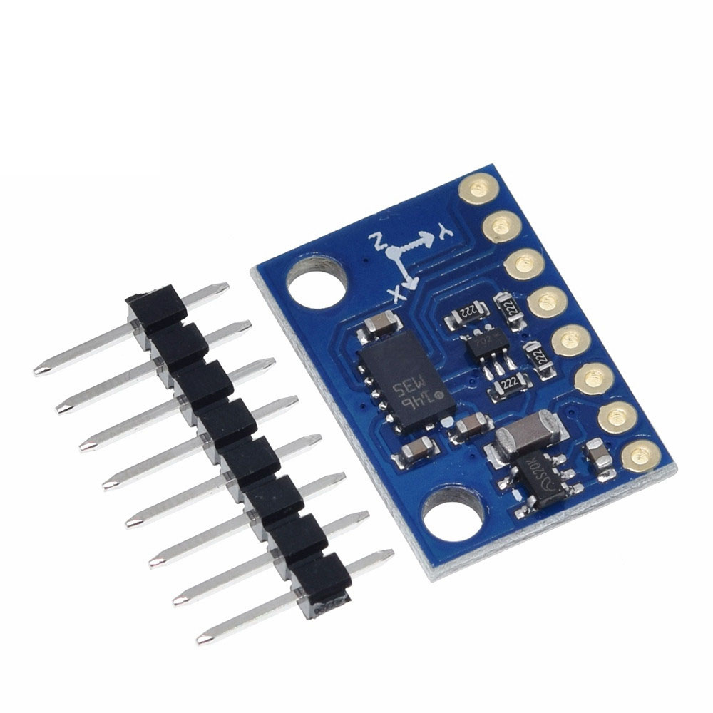
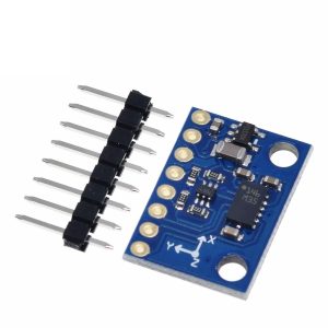
The GY-511 is a high-performance 6-degree-of-freedom (6DOF) sensor module that combines a 3-axis digital accelerometer and a 3-axis digital magnetometer in a single compact package. Built around the STMicroelectronics LSM303DLHC system-in-package, this module delivers both motion sensing and electronic compass functionality, making it an ideal solution for applications requiring precise orientation and heading detection.
The accelerometer component provides user-selectable full-scale ranges of ±2g, ±4g, ±8g, or ±16g, allowing you to measure both subtle tilt changes and significant impact events. The magnetometer offers seven selectable magnetic field ranges from ±1.3 to ±8.1 gauss, with a resolution down to 8 milligauss (mG), enabling accurate detection of the Earth’s magnetic field for reliable heading determination.
What sets the GY-511 apart from simpler magnetometer-only modules (such as the HMC5883L-based GY-271) is the inclusion of the 3-axis accelerometer. This accelerometer enables tilt-compensated compass functionality, where the module can calculate accurate heading even when the device is not held level. The accelerometer measures pitch and roll angles, which are then used to correct the raw magnetometer readings for accurate azimuth calculation.
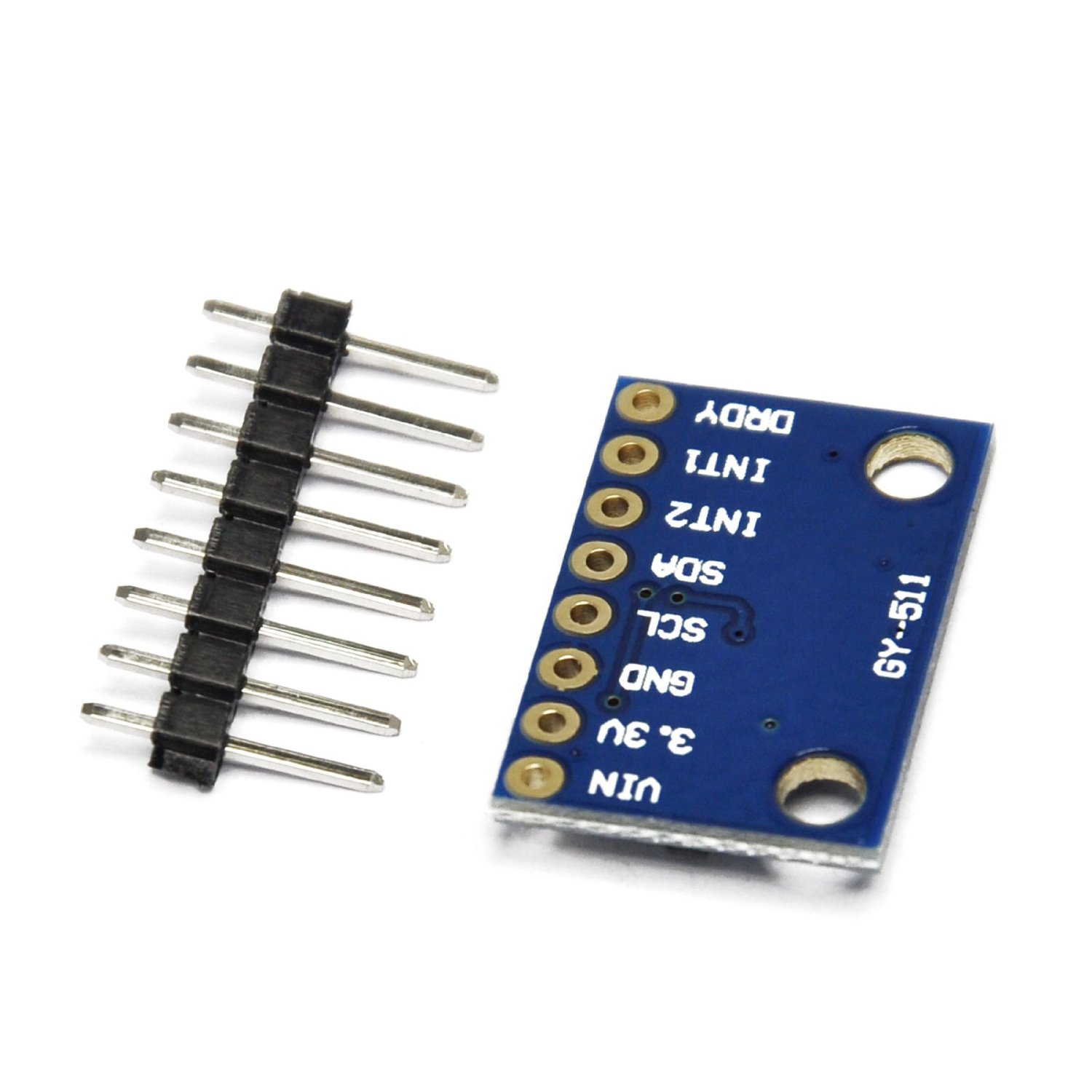
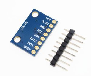
The module features an onboard 3.3V low-dropout voltage regulator, accepting input voltages from 3.6V to 6V DC, making it compatible with both 3.3V and 5V microcontroller systems. The I²C interface supports standard (100 kHz) and fast mode (400 kHz) communication speeds, ensuring seamless integration with Arduino, ESP32, STM32, Raspberry Pi, and other popular embedded platforms.
Additional features include two independent programmable interrupt generators for free-fall and motion detection, an embedded temperature sensor, and a built-in FIFO buffer for efficient data collection. The module also supports 6D/4D orientation detection, enabling applications such as display rotation and position-aware user interfaces.
Whether you are building a robotic navigation system, a tilt-compensated digital compass, a motion-activated controller, or a wearable step counter, the GY-511 LSM303DLHC module provides the precision, versatility, and ease of use required for both prototyping and production.
Key Features
-
6DOF Integration – Combines 3-axis accelerometer and 3-axis magnetometer in a single compact module
-
Tilt-Compensated Compass – Accelerometer enables accurate heading calculation when device is tilted
-
Selectable Measurement Ranges – ±2g/±4g/±8g/±16g acceleration; ±1.3 to ±8.1 gauss magnetic field
-
High-Resolution Output – 16-bit digital output for both accelerometer and magnetometer channels
-
I²C Digital Interface – Supports 100kHz and 400kHz communication speeds
-
Wide Voltage Compatibility – Onboard regulator accepts 3.6V to 6V DC input
-
Low Power Consumption – 110µA in normal mode; 1µA in idle/sleep mode
-
Programmable Interrupts – Two independent interrupt generators for free-fall and motion detection
-
Embedded Temperature Sensor – Provides onboard temperature monitoring
-
Additional Features – Embedded FIFO buffer, 6D/4D orientation detection
Technical Specifications
| Specification | Value |
|---|---|
| Sensor IC | LSM303DLHC (STMicroelectronics) |
| Operating Voltage | 3.6V – 6V DC (via onboard regulator) |
| Logic Voltage | 1.8V – 3.3V (3.3V output available from regulator) |
| Current Consumption | 110 µA (active), 1 µA (idle/sleep) |
| Acceleration Ranges | ±2g, ±4g, ±8g, ±16g (user-selectable) |
| Magnetic Ranges | ±1.3 / ±1.9 / ±2.5 / ±4.0 / ±4.7 / ±5.6 / ±8.1 gauss |
| Output Resolution | 16-bit data output |
| Interface | I²C (100kHz / 400kHz) |
| Operating Temperature | -40°C to +85°C |
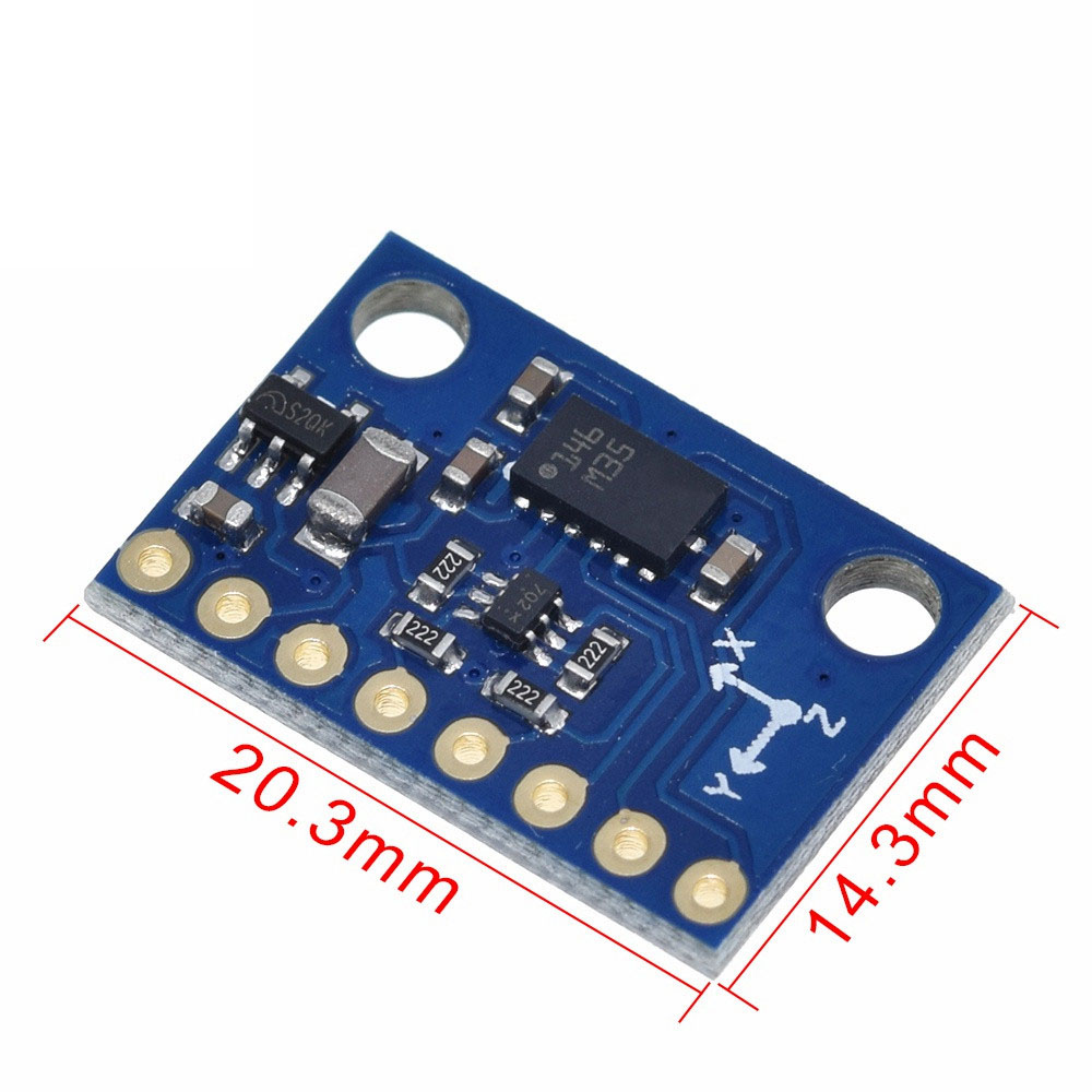
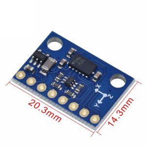
| Module Dimensions | 21mm × 14.5mm × 3.5mm (excluding pin headers) |


