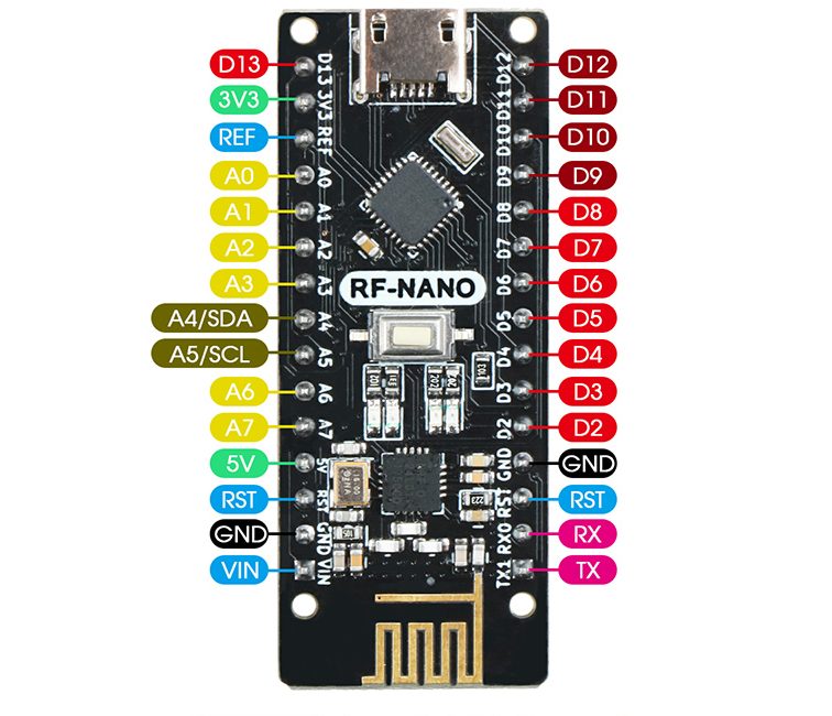
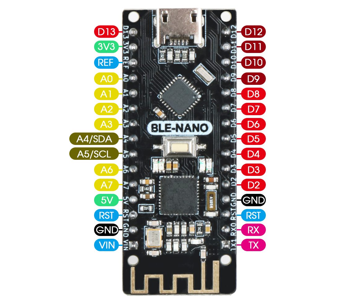
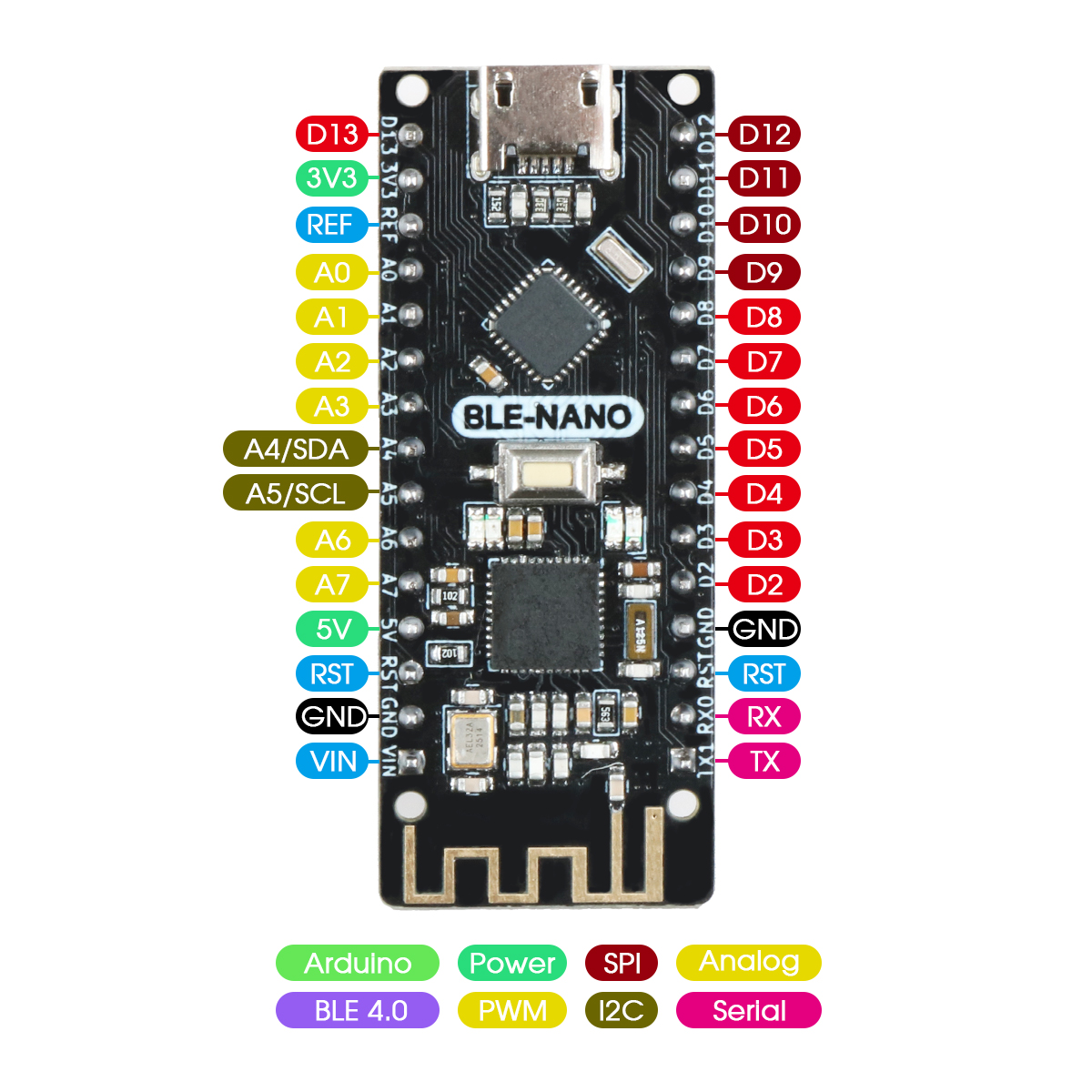
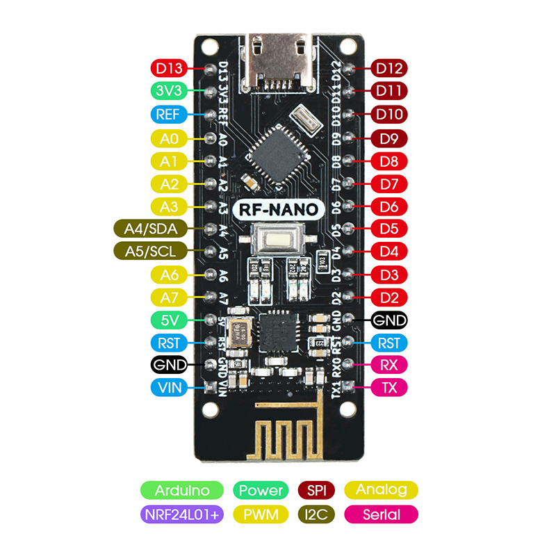
beemong

test

Flexible Trade Terms and Excellent After-Sale Service

For who responsible for international procurement, the product itself is very important, and trade terms and after-sales service are also particularly important considerations. Trade terms determine the flexibility of cooperation, and after-sales service will solve your worries.

In order to meet the needs of different customers, Beemong’s trade terms are very flexible, acceptable trade terms are: EXW, FOB, CIF, DDP etc. At the same time, for FOB, we can accept the freight forwarder designated by the customer.

For other express delivery, such as: Fedex, DHL, UPS, TNT, if the customer has his own account, we can cooperate with the customer’s account number for transportation. During the transportation process, we will regularly update the order progress to the customer, so that the customer can keep abreast of the transportation progress.

Payment methods can also be diversified, such as by T/T, L/C, Paypal, Western Union, MoneyGram, XTransfer, Alibaba, etc.

Although we try our best to avoid problems in any link of the transaction through management means, there may still be problems. We believe that creating problems is not the most terrible thing, but solving problems is the most important thing.

Another outstanding quality of Beemong lies in its corporate commitment, which has a lot to do with the management philosophy of the entire company. From the beginning of the establishment of the company, we have a firm belief that business is not a one-time transaction, we need to maintain the company for a long time. Therefore, helping customers solve problems is the premise and one of the most important values. When there is a problem, we will actively face and solve it. Whether it is caused by the customer or our own reasons, we always take solving the problem as the first principle, and then discuss the issue of responsibility attribution. This is why our major customers have cooperated for as long as 5 years or even longer is inseparable from our after-sales capabilities.

As a professional international purchaser, you may take an important position in the company or purchase for yourself, you shoulder the responsibility of being responsible for the product. Due to the long distance, many things cannot be checked in person, so it is very important to find a company with real transactions and real customers, as well as a partner who can solve problems together.

Our responsibility is, from the beginning of your cooperation with us, you can trust us with your purchasing needs. Maybe we are not the one with the lowest price, but we have been committed to making you the most at ease partner!

Excellent Patent in Education Robotic Kits

Excellent Patent in Education Robotic Kits

The gratifying news is that Beemong has cooperated with Mechanismic Inc. of the United States to develop our smart toy kit in 2022. It is the world’s first design-driven robotics education platform consisting of a

  • Patented hardware
  • APPs for designing robot motions and controlling them
  • Curriculum, tutorials, and professional development material, and
  • Educational services in the field of mechanical engineering, electronics, and computer programming in the context of engineering design.

We also offer camps, school and out-of-school educational programs for children from second grade to 12th grade.


Design-Driven Robotics Education

Mechanism design meets the classroom with MotionGen + Edurobotics.

Use the MotionGen app to draw a mechanism. Then, build it using Edurobotics.

Learn how to design structures and robots using our state of the curriculum. Learn on your own or use our educational services.

New Products Development

As the trading volume of our standard products tends to be stable and has a certain regularity, we can basically count and estimate the monthly and annual sales volume of some major products, and in the process of customer application, the contradiction between customer product demand and the limitations of standard products was further summarized, so the idea of optimizing products and producing Beemong’s own products came into being.

At present, we mainly carry out independent production for several major development versions, and formed: Uno, Nano, Mega and other products marked by Edurobotics. The main point of improvement is that some customers reported that it is very difficult to plug in the interface of the motherboard. We found that the quality of the USB port is different, so we will be extra strict in selecting and controlling the quality. For some orders with high requirements, we will ask employees to test the fit with the line before shipment.

We have re-customized and replaced some motor wires.

Some SG series motors have also been customized and optimized.

Experience Customized Business

Beemong started out as a trader, and established a solid foundation of trust during the cooperating with customers. Since some of our customers are brand owners, they need to customize products that fully meet their brand requirements, rather than standard products on the market. Therefore, we began to discuss how to cooperate, utilize China’s rich production resources, and realize brand value by reducing overall production costs and ensuring quality. Since 2018, we have transformed into a parallel development stage of trade and product customization.

Our most customized products are PCB and PCBA.

Our PCB factory has 15 years of PCB production experience and is a long-term strategic partnership with us. We worked together for 6 years. During these 6 years, we have completed government, schools and other commercial projects for many customers. The bidding process is usually very competitive. We have achieved success again and again by relying on our customer’s super negotiating ability, the company’s overall strength and our excellent production capacity. At the same time, the most important thing to thank is the trust and experience of our customers, which allows us to strive for excellence on the road of customization. Now our PCB customization business is very mature, you can rest assured to cooperate with us.

We have 3 PCBA factories with different specifications, which can meet different types of customer needs. One of our factories has 6 fully automatic SMT equipment, which can meet the production requirements of large quantities and high quality.

At the same time, we can customize the customer’s logo and specifications on the PCB to reflect the information of the brand identity, and can realize packaging customization, card customization, label customization, etc.

Our goal is to make every effort to help you realize the road of brand influence! Therefore, if you have any ideas and needs, please put them forward. I think as long as there is a demand, we can discuss and realize it together. On the road of development, it is easiest to obtain ordinary suppliers, and the hardest thing is to be willing to grow up with you and ascension’s strategic partner!

Strong and Stable Supply Chain

Beemong has been engaged in the export of educational electronic products for 8 years. Before founding Beemong, our founder Jesse and his friends jointly established another foreign trade enterprise of educational electronic products, and was responsible for supply chain management. During the process gradually have a comprehensive and substantive in-depth understanding of the industry supply chain, and have established a stable supply chain relationship.

After the establishment of Beemong, with the help of the Alibaba platform, we gradually developed and established a group of long-term cooperative customers. Most of these customers started with small trial orders and gradually developed to the stage of stable demand every month.It’s just a few simple words to summarize, but in fact, we have deep and unforgettable stories with every customer.

From business contact to sample confirmation to formal order, we have experienced repeated discussions and mutual confirmation. Customers need to confirm whether our product quality, order delivery date, and after-sales service are up to standard, and we also need to confirm whether customers’ payment is stable, assess the customer’s demand in order to establish an appropriate and reasonable inventory to shorten the order delivery time. Some customers’ products require additional certification, and we have also worked together to complete the process of multiple product destructive tests and corresponding qualification certification.

With the continuous growth of business volume, the needs of customers in various countries have also continuously prompted us to broaden our product categories. We have expanded from the original supply of educational electronic products to chips, tools, CNC series, 3D printing series, and motors. series, solar energy series, customized product series (including PCB and PCBA, plastic toy parts development, packaging customization, partial improvement of products), independent R&D product series, etc. Since the product levels required by different customers will also be different (this is related to our customers’ business chains in their business areas), we have also developed supply chains for different product levels.

Our supply chain system is divided into several categories:

Educational electronic products: Beemong cooperates directly with major domestic high-quality top-end single-chip motherboard manufacturers, ordinary electronic accessories manufacturers, STEM project-related accessories manufacturers or suppliers in order to obtain stable quality and competitive product prices. Due to the continuous growth of our business development and the stable and continuous demand of customers, the cooperation between us and suppliers is also very stable. Enjoying the VIP service they give us to our major customers, this value will ultimately benefit our customers.

Chip products: We have opened up multiple channels. We can not only supply big-name original imported chips, but also provide Chinese versions with reasonable prices and satisfactory functions for customers in need, so as to help customers reduce production costs. The production has verified that the quality is stable and can be used with confidence.

Tool products: We have long-term cooperation with well-known domestic multimeter manufacturers and various common tool manufacturers.

CNC series products: We mainly use small desktop CNC equipment (for the purpose of processing products in small processing factories, personal hobbyists and CNC education), and larger CNC equipment, which can be applied to cutting various common materials such as metal and wood.

3D printing series products: mainly supply smaller 3D printing equipment.

Motor series products: We provide standard motors for various intelligent robots, including various models and common colors, and also accept customization, such as replacing the motor line or other customizations to meet customer needs.

Solar series products: We mainly provide portable solar packs. Our factory accepts customizations such as style and power, and free samples are available.

Customized product series: We have our own PCB factory, which can customize various PCBs and process PCBA. For all kinds of our products, packaging customization and Logo printing can be realized.

Self-research and development: After years of precipitation, with the idea of developing an independent product line, we cooperated with the American team to develop a unique product (Edurobotics) that is different from LEEGO, and has obtained intellectual property rights certificates in multiple regions. At this stage, the whole series of products are in the final sprint before going on the market, and are expected to be available to global customers in the second half of the year.


Micro:bit IO Expansion Board

Introduction to IO:bit
The IO:bit expansion board is a powerful microbit expansion board. It leads out 19 PIN pins of the microbit main board. Each PIN pin has VCC and GND corresponding to it. The VCC can be freely switched to 3V3 or 5V through the jumper cap. ;Contain 3 independent 3V3 and 5V pins, the wiring method is more flexible and diverse; In addition, the SDA and SCL pins of I2C, as well as the corresponding 5V and GND pins, are provided for the connection of modules such as LCD1602 liquid crystal display screen of I2C communication. Multiple possibilities; on-board passive buzzer, connected through jumper caps; power supply methods include DC head and USB socket power supply.

IO:bit parameter

PCB board thickness: 1.6mm
Small hole diameter: 3.0mm
Large round hole diameter: 4.6mm (compatible with Lego holes)
Product Size: 57mm/39mm/15mm
Net weight: 18.7g
USB input voltage: 5V
DC head input voltage: 6-12V

Product physical map
IO:bit expansion board and microbit motherboard

IO:bit

IO:bit pin introduction
IO:bit expansion board front function diagram

19 PIN pins

19PIN

In the design process of IO:bit, it is fully considered that for developers who want to use the microbit pins deeply, all the IO ports of the microbit are drawn out, and each PIN pin has a corresponding label and a simple identification of the pin function. The blue lines of the pins represent IO pins, the red lines represent VCC, and the black lines represent GND. Among them, the passive buzzer is connected to the P0 pin through the jumper cap.

3V3, 5V pins

In the process of developing with microbit, if you use a module that requires 5V voltage, you can connect it to the 5V interface of the expansion board through a DuPont cable; if you need a 3V3 voltage module, you can connect it to the 3V3 interface of the expansion board through a DuPont cable.

Introduction of jumper caps

The IO:bit expansion board has two jumper caps. The first jumper cap is used to control the VCC voltage value of the IO pin in the expansion board. You can choose to connect 3V3 or 5V. The second jumper cap is used to control the board. For the passive buzzer, when the jumper cap pin is the Buzzer pin, the onboard passive buzzer is connected to the P0 pin of the microbit, and the corresponding music can be played through the microbit graphical music program building block.

I2C pins

The 19-way PIN pins of the IO:bit expansion board already include the P19 and P20 pins for I2C communication. In order to be more flexible and convenient to use, a complete I2C communication pin is specially designed for I2C communication. 4 pins, 5V pin, SCL pin, SDA pin, GND pin.

Power socket

The IO:bit expansion board has two power supply modes. During use, it can be powered by USB or the battery of the DC head. When the expansion board is powered on, the on-board red power indicator will light up.


Microbit Introduction

Microbit_all..png

Product introduction
Microbit is a microcomputer for youth programming education launched by the British BBC. The board size is only half the size of a credit card, but it integrates an acceleration sensor, a magnetic sensor, two programmable buttons, 25 monochrome LEDs, Bluetooth and other commonly used sensors equipment. Microbit uses the micro usb interface for power supply, and can be connected to an external battery box. There are multiple gold finger pins at the bottom of the motherboard, which is convenient for external control devices. Whether it’s a robot or a musical instrument, Microbit can realize any cool little inventions. You can use Microbit to write video games, realize sound and light interaction, do scientific experiments, control small robots, and calculate math problems. Microbit provides an online programming website for online programming through graphical or python or JavaScript programming languages, supporting almost all PC and mobile devices.

suitable for the crowd
Microbit can perform graphical programming, and users without programming foundation can easily start. On the other hand, Microbit can also perform JavaScript and python code programming, fully exercise the programming thinking of primary and secondary school students, and improve the programming ability of primary and secondary school students.

Structure introduction

microbit_structure_zh.png

technical parameter
Working voltage: 3V
Output current: 40ma
Power supply mode: power supply through micro usb interface, or use Microbit’s 3V battery box interface to supply power
Program download: use the micro usb data cable to download the program
Pin lead out: The control pin is led out through the golden finger at the bottom, including an I2C, an SPI, and a serial port through the IO port. (I2C function pins are 19 and 20, these two pins cannot be read and written as ordinary IO, only I2C communication can be performed)
Onboard devices: three-axis accelerometer, magnetometer, 3 physical buttons (A/B/reset), 5×5 dot matrix screen (25 LED lights), Bluetooth/2.4G communication, temperature detection (inside the Bluetooth chip), light Strength detection (reverse diode current)

functional module
Programmable LED Screen
25 red LED lights form a 5×5 dot matrix, which can display various graphics. When programming the LED screen, you can choose to use the official built-in graphics library, such as various emoticons, or you can design graphics on the screen yourself show.

microbit_face.gif

Programmable keys
There are two programmable buttons A and B on the front of the Microbit. In the programming languages supported by the Microbit, there are control blocks or commands for these two buttons, and the three button states can be detected through the program.

Gold finger pin
The gold fingers at the bottom of the Microbit motherboard lead out all the pins supported by Microbit, and are designed with metal ring holes, which can be connected to external devices through alligator clips or 4mm banana plugs to control servos, motors, etc.
Microbit cheat pins include 19 GPIOs that can be set, namely: P3, P0, P4-P7, P1, P8-P12, P2, P13-P16, 3V (3), P19-P20, GND (3) .
Can be set out: 3 PWM outputs, 1 pair of UART serial transceivers, 1 SPI bus (P13-P15), 1 I2C bus (P19-P20). P3, P4, P6, P7, P9, P10 are used to control the LED screen of the main board, and P5 and P11 are used to control the A and B buttons of the main board.

Microbit_pin.png

reset button
There is a reset button on the back of the Microbit. When the program needs to be restarted, press the reset button, and the downloaded program will run from the beginning.

microbit_reset.png

USB interface
There is a micro usb interface on the back of the Microbit, which is mainly used to download control programs and power the motherboard. When downloading the program, one end of the data cable of the micro usb interface is connected to the USB interface of the computer, and the other end is connected to the usb interface of the Microbit.

microbit_usb.png

Battery box interface
Microbit is designed with a battery compartment connector, which can be used to power the Microbit motherboard. It should be noted that the power supply voltage of the Microbit motherboard is 3V, so when using the battery box interface to power the Microbit, the voltage should be 3V. If it is too high, the motherboard will be damaged, and if it is too low, it cannot be driven.

microbit_3V.png

Bluetooth communication
Microbit is designed with bluetooth communication function, which can control Microbit through bluetooth, for example, control the display pattern of Microbit screen through the bluetooth signal of mobile phone.

microbit_bluetooth.png

2.4G wireless
Microbit motherboards can also communicate wirelessly through the 2.4G wireless function, and the official provides corresponding wireless communication blocks and commands, which are easy to operate.

microbit_2.4G.png

temperature check
The Microbit motherboard is not designed with a temperature sensor. The temperature detection uses the temperature detector inside the Bluetooth chip. The temperature detection function is achieved by detecting the internal temperature of the chip.

microbit_TEMP.png

light intensity detection
How does the Microbit motherboard detect light intensity? Mainly through the action of the reverse diode current under the LED screen, it is converted into a photosensitive sensor for light intensity detection.

microbit_brightness.png

3-axis acceleration
The Microbit motherboard contains a 3-axis accelerometer that detects angular and acceleration changes in three-dimensional states. And the official encapsulates different status data, you can directly select the corresponding status blocks or commands in the process of use, which reduces the problem of data processing and improves the operability.

microbit_accelerated.png

magnetometer
The Microbit motherboard contains a magnetic sensor, which can not only detect changes in the surrounding magnetic field strength during use, but also be used as a compass to display different angles in different directions to indicate orientation.

microbit_magnetometer.png

1602LCD Specifications

Block Diagram

LCD1602

Overview
​ LCD1602 is a character LCD module specially used to display letters, numbers and symbols. It is widely used in industry, such as electronic clock, temperature display. Most of the character LCDs on the market are based on the HD44780 character LCD chip, and the control principle is exactly the same. “1602” means 2 lines and 16 characters per line. The LCD1602 display screen with the adapter board uses the IIC interface, which saves a lot of I/O ports. 1602 Liquid Crystal Display (1602 Liquid Crystal Display, hereinafter referred to as 1602 LCD) is a common character liquid crystal display, because it can display Named after 16*2 characters. Usually, the 1602 LCD we use integrates the font chip. Through the API provided by the LiquidCrystal class library, we can easily use the 1602 LCD to display English letters and some symbols.

Schematic

9

Module parameters
Pin Name    Description
GND         5V power supply pin
VCC             GND ground
SDA             data pin
SCL             clock pin

Detailed schematic

1602


0


Hummer-bot4.0 usage overview

Product introduction
“Hummer-Bot” is a multi-function car based on BLE-UNO as the core control and MX1616L as a motor-driven car. Compared with traditional cars, “Hummer-Bot” is also equipped with wireless control (Bluetooth, infrared, etc.); ultrasonic, etc. . It can automatically track and avoid obstacles. Of course, Hummer-Bot can also be controlled wirelessly. Make full use of each module and integrate various related sensors to make the car more intelligent; more meaningful for development; more challenging. “Hummer-Bot” is equipped with various materials, technical manuals, routines, etc., to teach you from entry to mastery. Every electronic hobbyist can easily get started and realize the functions they want.

Product parameters
Three-way infrared black line tracking module
2 sets of infrared obstacle avoidance and light tracking modules
1 ultrasonic obstacle avoidance with steering gear
4-way DC motor drive
2 2000mA, 3.7v rechargeable lithium batteries for longer battery life
Support real-time detection of battery power
Support infrared remote control
Support bluetooth app control
Support PS2 handle control (optional)
Support nRF24L01+ wireless control (optional)
Support wifi control (optional)

Preparation

About Arduino BLE-UNO main control board and expansion board
Arduino BLE-UNO main control board

In “Hummer-Bot”, we used BLE-UNO as the main control board, it has 14 digital input/output pins (6 of which can be used as PWM output), 6 analog inputs, 1 16 MHz ceramic resonator device, 1 USB connection, 1 power socket, 1 ICSP header and 1 reset button. It includes everything you need to support your microcontroller; just connect it to a computer via a USB cable or power it with an AC-DC adapter or battery to get started. In addition, there is also a CC2540 Bluetooth module onboard, which can realize Bluetooth communication.

1

Technical Specifications
Working voltage: 5V
BLE chip: TI CC2540
BLE working channel 2.4G
Bluetooth transmission distance: open distance 50m
Support AT command to configure BLE
Support USB virtual serial port, hardware serial port, BLE three-way transparent transmission
Bluetooth supports master-slave switching
Support Bluetooth automatic connection to slave in master mode
Support sending more than 20 bytes.
Support iBeacons
Interface: Micro-USB
Input voltage: USB powered or external 7V~12V DC input
Output voltage: 5V DC output and 3.3V DC output and external power input
Microprocessor: ATmega328 (chip data sheet in the supporting materials)
Bootloader: Arduino Uno
Clock Frequency: 16 MHz
Support USB interface protocol and power supply (no external power supply required)
Support ISP download function
Digital I/O ports: 14 (4 PWM outputs)
Analog input ports: 6
DC current I/O port: 40mA
DC current 3.3V port: 50mA
Flash memory: 32 KB (ATmega328) (0.5 KB for bootloader)
SRAM: 2 KB (ATmega328)
EEPROM: 1 KB (ATmega328)
Bootloader: latest Arduino1.8.8
Dimensions: 75x55x15mm
Expansion board interface diagram

2

When installing the steering gear, pay attention to the steering gear, please read the description of the steering gear calibration section first.

4

Hummer Bot Module Experiment
Motor drive principle
In the “Hummer-Bot” car, we chose 4 DC geared motors as the power, and MX1616L as the motor driver chip.

MX1616L adopts H-bridge circuit structure design, and adopts high-reliability power tube technology, which is especially suitable for driving coils, motors and other inductive loads. The circuit integrates N-channel and P-channel power MOSFETs, and the operating voltage range covers 2-10V, 27°C, VDD=6.5V. Under the condition of two channels working at the same time, the maximum continuous output current of one channel reaches 1.2A, the maximum The peak output current reaches 2.5A; the maximum continuous output current of 2 channels reaches 1.2A, and the maximum peak output current reaches 2.5A.

5

MX1616L can drive 2 motors, 2 motors are connected between OUTA1, OUTB1 and OUTA2, OUB2 respectively. Pins 2, 3, 6, and 7 are connected to the input control level to control the forward and reverse rotation and stop of the motor. Its features are:

Low standby current (less than 0.1uA)

Low on-resistance MOSFET power switch

Internally integrated freewheeling diode

small input current

Can control two DC motors

A single stepper motor can be controlled

Can realize forward and reverse.


6

Schematic diagram of motor driver board

7

Motor driver board wire connection
By looking at the chip information, we know that BLE-UNO has 6 PWM interfaces, which are digital interfaces 3, 5, 6, 9, 10, and 11. Here, we choose 5, 6, 9, and 10 as the motor control IO, and their connections are shown in the figure. The wiring method of the motor driver board and the arduino expansion board is as follows:

8

Infrared obstacle avoidance and light seeking module introduction
The infrared obstacle avoidance and light search module integrates the infrared obstacle avoidance function and light search function on one module. The infrared obstacle avoidance function transmits infrared signals through the infrared emission tube on the module. When the infrared signal encounters obstacles, it is sent back. , the infrared receiver tube receives the reflected infrared signal, so as to judge that there is an obstacle and achieve the purpose of obstacle avoidance. The light-seeking function is realized by using the photoresistor on the module. When the photoresistor is irradiated by strong light, its resistance value drops rapidly, the passing current increases, and the resistance value of the photoresistor increases rapidly in the dark environment, and the passing current decreases. Small, the main control board uses this to determine whether there is a light source.

How infrared obstacle avoidance works
The infrared obstacle avoidance and light search module has a pair of infrared emission and reception tubes. The emission tube emits infrared rays of a certain frequency. When the detection direction encounters an obstacle (reflecting surface), the infrared rays are reflected back and received by the receiving tube, and pass through the comparator. After the circuit is processed, the green indicator light will light up, and the signal output interface will output a digital signal (a low-level signal). The detection distance of the sensor can be adjusted by a potentiometer. Since infrared rays are used, the anti-interference ability is very strong, and the measurement accuracy is very high when the distance is moderate. In addition, the module is easy to assemble and use, and can be widely used in many occasions such as robot obstacle avoidance, obstacle avoidance trolley, assembly line counting and black and white line tracking.

How light works
The light-seeking function of the infrared obstacle avoidance and light-seeking module is to judge the light intensity of the surrounding environment through the photodiode, and output an analog signal. When the photoresistor is irradiated by strong light, its resistance value drops rapidly, the passing current increases, the resistance value of the photoresistor increases rapidly in a dark environment, and the passing current decreases, and the main control board judges whether there is a light source. Working voltage: 0.3-10V. Since the SG-PT3528 photodiode is used, it can simulate the sensitivity of the human eye, with a peak sensitivity wavelength of 590nm, anti-infrared interference, fast response speed and stable performance. In addition, the module is easy to assemble and use, and can be widely used in night lights, lawn lights, sun lights, etc.

Infrared obstacle avoidance and light seeking module parameters
Working voltage: 5V
Infrared detection effective distance range: 2 ~ 30cm
Peak photosensitive wavelength: 590nm
Output infrared obstacle avoidance signal: digital signal
Output photosensitive signal: analog signal

9

The module can adjust the infrared obstacle avoidance detection distance through the potentiometer, and the detection distance is 2~30cm. If you find that the distance measurement is not very sensitive during use, you can use the trimmer potentiometer to achieve the desired result (adjust the potentiometer clockwise, the detection distance Increase; adjust the potentiometer counterclockwise to reduce the detection distance), the infrared obstacle avoidance detection distance on the left and right sides needs to be adjusted the same, so that the car will be more smooth during the obstacle avoidance process.

Manual adjustment as shown in the figure:

10

11

Infrared obstacle avoidance and light-seeking module wire connection

12


Detailed descriptions of RF-Nano

Overview of RF-NANO
The NRF24L01+ chip is integrated on the RF-NANO board, which makes it have unlimited transceiver functions, which is equivalent to combining an ordinary Nano board and an NRF24L01 module into one, which is more convenient to use and small in size. The RF-NANO has exactly the same pins as the common Nano board, which is easy to transplant.

Introduction of RF-NANO Processor
Arduino RF-NANO microprocessor is ATmega328 (Nano3.0) with USB-Micro interface, 14 digital input/output ports (6 of which can be used as PWM output), 8 analog inputs, and a 16MHz crystal oscillator , a USB-Micro port, an ICSP header and a reset button. * Processor: ATmega328 * Operating voltage: 5V * Input voltage (recommended): 7-12V * Input voltage (range): 6-20V * Digital IO pins: 14 (6 of which are used as PWM outputs) (D0~D13) * Analog input pins: 6 (A0~A5) * IO pin DC current: 40mA * Flash Memory: 32KB (2KB of which is used for bootloader) * SRAM: 2KB * EEPROM: 1KB (ATmega328) * USB to serial port chip: CH340 * Working Clock: 16MHZ

Power Supply
Arduino RF-Nano power supply mode: Micro – USB interface power supply and external vin connected to 7~12V external DC power supply

Memory
ATmega328 includes on-chip 32KB Flash, of which 2KB is used for Bootloader. There are also 2KB SRAM and 1KB EEPROM.

Input Output
14 digital input and output ports: The working voltage is 5V, and each channel can output and access the maximum current of 40mA. Each channel is configured with a 20-50K ohm internal pull-up resistor (not connected by default). In addition to this, some pins have specific functions.Serial port signal RX (No. 0), TX (No. 1): Provide the serial port receiving signal of TTL voltage level, and connect with the corresponding pin of FT232Rl.
External interrupt (No. 2 and No. 3): Trigger the interrupt pin, which can be set to trigger on the rising edge, falling edge or both.
Pulse width modulation PWM (3, 5, 6, 9, 10, 11): Provide 6 8-bit PWM outputs.
SPI (10(SS), 11(MOSI), 12(MISO), 13(SCK)): SPI communication interface.
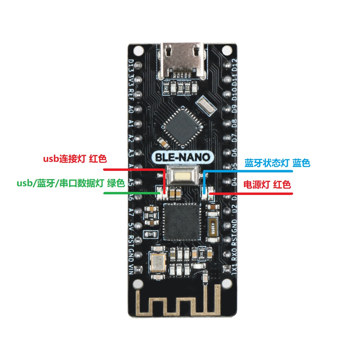
LED (No. 13): Arduino is specially used to test the reserved interface of the LED. When the output is high, the LED is turned on, otherwise, the LED is off when the output is low.
6 channels of analog input A0 to A5: each channel has a resolution of 10 bits (that is, the input has 1024 different values), the default input signal range is 0 to 5V, and the upper limit of the input can be adjusted through AREF. In addition to this, some pins have specific functions.
TWI interface (SDA A4 and SCL A5): support communication interface (compatible with I2C bus).
AREF: The reference voltage of the analog input signal.
Reset: Reset the microcontroller chip when the signal is low.

Communication Interface
Serial port: The built-in UART of ATmega328 can communicate with the external serial port through digital ports 0 (RX) and 1 (TX).

Communication between ATmega328 and NRF24L01+
ATmega328 and NRF24L01+ are SPI communication, the schematic diagram is shown in the figure:

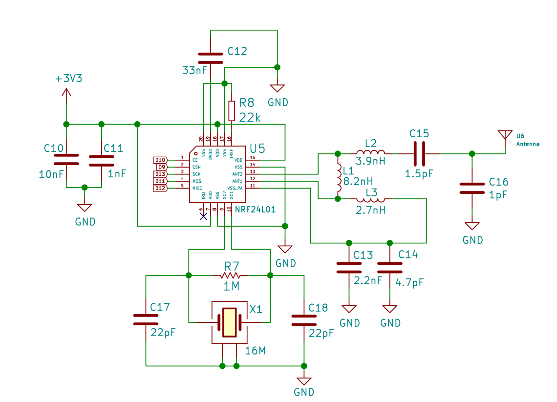
ATmega328 and NRF24L01+ chip pin connections:

ATmega328 chip NRF24L01+ chip
+3.3V VCC
GND GND
D9 CSN
D10 CE
D11 MOSI
D12 MISO
D13 SCK
Note: The D9, D10, D11, D12, D13 pins that have been occupied by ATmega328 can no longer be reused.

Downloader
The MCU on the Arduino RF-Nano has a preset bootloader program, so the program can be downloaded directly through the Arduino IDE software. You can also directly download the program to the MCU through the ICSP header on the RF-Nano.

Points to Note
The Arduino RF-Nano provides an automatic reset design that can be reset by the host. In this way, the software can be automatically reset in the RF-Nano through the Arduino software, and there is no need to press the reset button.
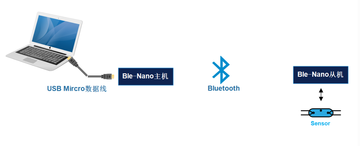
 

How RF-NANO works
Introduction to the working principle of RF-NANO
RF-NANO can transmit data as well as receive data.

When transmitting data: First configure NRF24L01+ to transmit mode: then write the receiving node address TX_ADDR and valid data TX_PLD into the NRF24L01+ buffer area from the SPI port according to the timing, TX_PLD must be written continuously when CSN is low, and TX_ADDR is written when transmitting Enter once, and then set CE to high level and keep it for at least 10μs, and then transmit data after a delay of 130μs; if the automatic response is turned on, then NRF24L01+ will enter the receiving mode immediately after transmitting data, and receive the response signal (the automatic response receiving address should be the same as the receiving address). The node address TX_ADDR is the same). If a response is received, the communication is considered successful, TX_DS is set high, and TX_PLD is cleared from the TX FIFO; if no response is received, the data is automatically retransmitted (automatic retransmission is enabled), ) reaches the upper limit, MAX_RT is set high, and the data in the TX FIFO is reserved for the next retransmission; when MAX_RT or TX_DS is set high, the IRQ becomes low, an interrupt is generated, and the MCU is notified. When the last transmission is successful, if CE is low, the NRF24L01+ enters idle mode 1; if there is data in the transmission stack and CE is high, it enters the next transmission; if there is no data in the transmission stack and CE is high, it enters idle mode 2.

When receiving data: First configure the NRF24L01+ to receive mode, then delay 130μs to enter the receive state and wait for the arrival of data. When the receiver detects a valid address and CRC, it stores the data packet in the RX FIFO, and at the same time, the interrupt flag bit RX_DR is set high, the IRQ becomes low, an interrupt is generated, and the MCU is notified to fetch the data. If the automatic response is turned on at this time, the receiver will enter the transmitting state at the same time and return the response signal. When the last reception is successful, if CE becomes low, the NRF24L01+ enters idle mode 1.

Be sure to enter standby mode or power-down mode before writing to the registers. the SPI operation and timing diagram are given
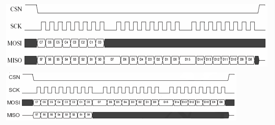
configuration word
The SPI port is a synchronous serial communication interface with a maximum transmission rate of 10 Mb/s. During transmission, the low-order byte is transmitted first, and then the high-order byte is transmitted. But for a single byte, the high bit must be sent first and then the low bit. There are 8 instructions related to SPI, and these control instructions are input by MOSI of NRF24L01+ when used. Corresponding status and data information is output from MISO to MCU.

All configuration words of nRF24L0l+ are defined by configuration registers, which can be accessed through the SPI port. There are 25 configuration registers in NRF24L01+, and the commonly used configuration registers are shown in Table 2.

Table 2: Common Configuration Registers

Add Name Function
00 CONFIG Set the working mode of NRF24L01+
01 EN_AA Set receive channel and auto answer
02 EN_RXADDR Enable receive channel address
03 SETUP_AW Set address width
04 SETUP_RETR Set the time and times to automatically resend data
07 STATUS Status register, used to determine the working status
0A~0F RX_ADDR_P0~P5 Set receive channel address
10 TX_ADDR Set the receiving contact address
11~16 RX_PW_P0~P5 Set the effective data width of the receive channel

Address Register Name Function
00 CONFIG Set the working mode of NRF24L01+
01 EN_AA Set the receiving channel and automatic answering
02 EN_RXADDR Enable receive channel address
03 SETUP_AW Set address width
04 SETUP_RETR Set the time and times of automatic data retransmission
07 STATUS status register, used to determine the working status
0A~0F RX_ADDR_P0~P5 Set receive channel address
10 TX_ADDR Set receive contact address
11~16 RX_PW_P0~P5 Set the effective data width of the receive channel
The working mode of RF-NANO
There is a state machine inside the NRF24L01+ chip, which controls the transition of the chip between different working modes. NRF24L01+ can be configured as Shutdown, Standby, Idle-TX, TX and RX five working modes.

Shutdown working mode:

In Shutdown working mode, all transceiver function modules of NRF24L01+ are turned off, the chip stops working, and consumes the least current, but all internal register values ​​and FIFO values ​​remain unchanged, and the registers can still be read and written through SPI. Set the value of the PWR_UP bit of the CONFIG register to 0, and the chip returns to the Shutdown working mode immediately.

Standby working mode:

In Standby mode, only the crystal oscillator circuit works, which ensures that the chip can start up quickly while consuming less current. Set the value of the PWR_UP bit in the CONFIG register to 1, and the chip will enter Standby mode after the clock is stable. The clock stabilization time of the chip is generally 1.5~2ms, which is related to the performance of the crystal oscillator. When pin CE=1, the chip will enter Idle-TX or RX mode from Standby mode, and when CE=0, the chip will return to Standby mode from Idle-TX, TX or RX mode.

Idle-TX working mode:

In the Idle-TX working mode, the crystal oscillator circuit and the clock circuit work. Compared to Standby mode, the chip consumes more current. When the transmitter TX FIFO register is empty and pin CE=1, the chip enters into Idle-TX mode. In this mode, if a new data packet is sent to the TX FIFO, the circuit inside the chip will start immediately and switch to the TX mode to send the data packet. In Standby and Idle-TX operating modes, all internal register values ​​and FIFO values ​​remain unchanged, and registers can still be read and written through SPI.

TX working mode:

When you need to send data, you need to switch to the TX working mode. The conditions for the chip to enter the TX working mode are: there is data in the TX FIFO, the value of the PWR_UP bit in the CONFIG register is 1, the value of the PRIM_RX bit is 0, and there is a high pulse on pin CE that lasts at least 10us. The chip will not directly switch from Standby mode to TX mode, but immediately switch to Idle-TX mode, and then automatically switch to TX mode from Idle-TX mode. The time to switch from Idle-TX mode to TX mode is between 120us and 130us, but will not exceed 130us. After a single packet of data is sent, if CE=1, the working mode of the chip is determined by the state of the TX FIFO. When there is data in the TX FIFO, the chip continues to remain in the TX working mode and sends the next packet of data; when If there is no data in the TX FIFO, the chip returns to Idle-TX mode; if CE=0, it returns to Standby mode immediately. After the data transmission is completed, the chip generates a data transmission completion interrupt.

RX working mode:

When it needs to receive data, it needs to switch to RX working mode. The conditions for the chip to enter the RX working mode are: set the value of the PWR_UP bit of the register CONFIG to 1, the value of the PRIM_RX bit to 1, and the pin CE=1. The time for the chip to switch from Standby mode to RX mode is 120~130us. When the address of the received data packet is the same as the address of the chip, and the CRC check is correct, the data will be automatically stored in the RX FIFO, and a data reception interrupt will be generated. The chip can store up to three valid data packets at the same time. When the FIFO is full, the received data packets are automatically discarded. In receive mode, the received signal power can be detected through the RSSI register. When the received signal strength is greater than -60dBm, the value of the RSSI bit in the RSSI register will be set to 1. Otherwise, RSSI=0. There are two ways to update the RSSI register: when a valid data packet is received, the RSSI will be automatically updated, and the RSSI will also be automatically updated when the chip is switched from RX mode to Standby mode. The value of RSSI varies with temperature within ±5dBm.

Detailed descriptions of BLE-Nano board

Product introduction
Ble-Nano is a revolutionary product developed by emakefun for makers based on the perfect combination of Bluetooth 4.0 protocol and Arduino NanoV3.0. Its functions and pins are fully compatible with traditional Arduino NanoV3.0 motherboards. The working frequency band is 2.4GHZ and the modulation method is GFSK, the maximum transmission power is 0db, and the maximum transmission distance is 50 meters. It adopts imported original TI CC2540 chip design. It supports users to modify and view the device name, service UUID, transmission power, pairing password and other commands through AT commands, which is convenient, quick and flexible to use. The product is very small in size, suitable for many applications with strict size constraints.

We provide Android and IOS mobile phone demos, you can quickly develop a hardware device that communicates with mobile phones.

Just like the very popular wearable mobile phone peripherals, all of them can be developed on the Ble-Nano platform. You can use Ble-Nano to connect with Bluetooth 4.0 devices, realize wireless transmission between two Bluetooth devices, and set master and slave devices. .Even establish a Bluetooth HID connection with PC. At the same time, we provide developers with great freedom and support preparation. Users can not only debug the Ble-Nano through AT commands, but also add Arduino-compatible expansion boards, sensors, motors, and servos to the Ble-Nano controller. Drivers, etc., emakefun exclusively developed the function of automatically connecting to the slave in the Bluetooth master mode, and supports more than 20 bytes of transmission, which is more convenient to use.

Product parameters
Fully compatible with Arduino Nano V3.0 pins and usage
BLE chip: TI CC2540
Working channel 2.4G
Transmission distance: open distance 50m
Support AT command to configure BLE
Support USB virtual serial port, hardware serial port, BLE three-way transparent transmission
Support master-slave switching
Support Bluetooth automatic connection to slave in master mode
Support more than 20byte sending, automatic subcontracting.
Interface: Mirco-Usb
Input voltage: Usb power supply, Vin6~12V, 5V
Microprocessor: ATmega328P-MU QFN32
Bootloader: latest Arduino1.8.8
Pin: Two rows of 2.54mm-15Pin
Dimensions: 48mm x 19mm x 12mm
Weight: 18g


Indicator light description
When the bluetooth is not connected, the blue light flashes, and the blue light is always on after connecting
When there is bluetooth data communication or usb has data, or Ble-Nano serial port data, the green light flashes
When the USB data cable is successfully connected, the usb light is on. If only the power light is on after the usb is connected, but the usb indicator is not on, it means that the USB-Micro cable is bad, please replace it

Development Notes
Because the bluetooth of the product is a transparent transmission function, bluetooth programming is actually reading and writing to the serial port of the arduino. We need to pay attention to two points when programming. 1. The BLE protocol stipulates that the length of each bluetooth data packet cannot exceed 20bytes. Our bluetooth The module does packet transmission, but there is a low probability of packet loss, so when the size exceeds 20 bytes, the audino packet transmission is the most reliable. 2. The data sending interval of each packet needs to exceed 150ms, otherwise it is easy to lose packets.

Ble-Nano master-slave communication and practical application combined with Processing
Many times we use Ble-Nano and Processing to complete our own ideas, so the simplest solution is as follows