Product Overview
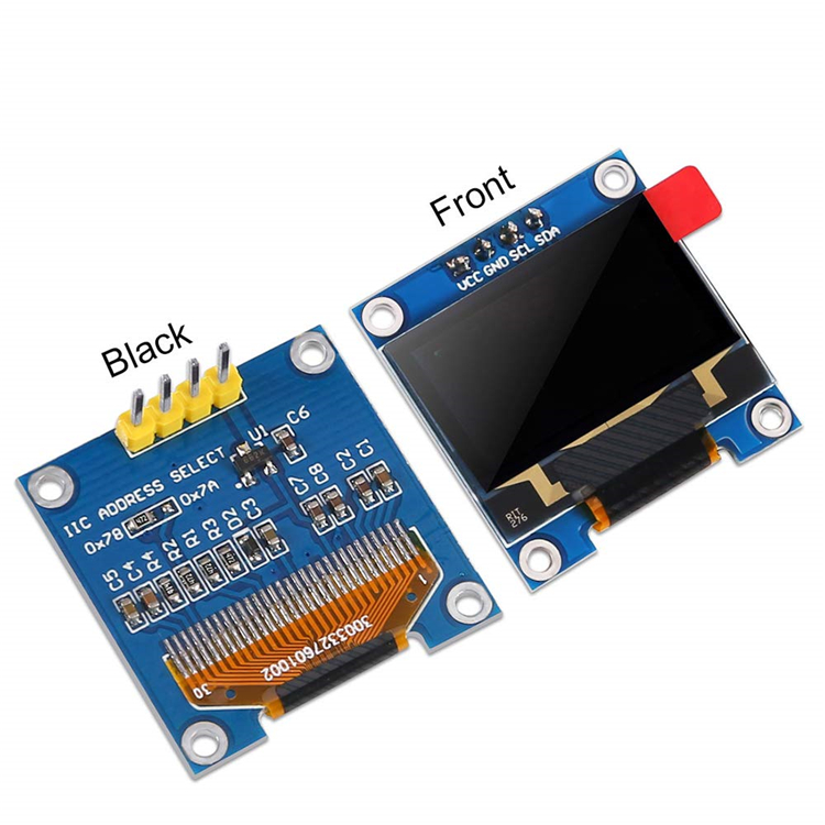
The 0.96″ Inch I2C OLED Display Module is a compact, high-contrast monochrome screen designed for electronics projects requiring visual output without consuming excessive power or I/O pins. Based on the SSD1306 driver IC, this 4-pin module features a 128×64 pixel resolution and communicates via the simple I2C protocol, requiring only two data lines (SDA and SCL) to operate .
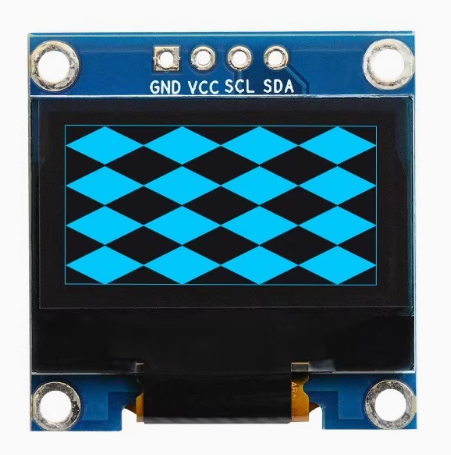
OLED (Organic Light Emitting Diode) technology differs from traditional LCDs in that each pixel emits its own light. This allows for true blacks (pixels are completely off), resulting in exceptional contrast ratios and wide viewing angles. The blue monochrome display provides crisp, high-visibility characters and graphics that stand out clearly against the dark background.
The 4-pin design (VCC, GND, SCL, SDA) is specifically optimized for simplicity—it can be connected directly to your microcontroller with just four jumper wires, making it an ideal choice for beginners, rapid prototyping, and space-constrained projects . The module operates on either 3.3V or 5V logic, ensuring compatibility with Arduino, ESP32, ESP8266, Raspberry Pi, STM32, and most other development boards .
Key Features
-
128×64 Pixel Resolution: Displays up to 8 lines of 21 characters (with default font) or custom graphics, icons, and bitmaps
-
SSD1306 Driver IC: Industry-standard controller with integrated oscillator and charge pump for simplified driving circuitry
-
I2C Interface: Only 2 data pins (SDA, SCL) needed, saving valuable I/O pins for other sensors and peripherals
-
3.3V/5V Compatible: Built-in voltage regulator accepts both logic levels – works with 5V Arduino and 3.3V ESP32/ESP8266 without level shifting
-
Ultra-Low Power Consumption: OLED pixels emit their own light – no backlight needed. Typical operating current ~20mA
-
True Black Background: Inactive pixels are completely off, providing exceptional contrast and a professional appearance
-
Wide Viewing Angle: >160° visibility from any direction – no contrast shift when viewing from the side
-
Pre-soldered 4-Pin Header: Ready to use out of the box – no soldering required for breadboard prototyping
-
Compact Size: Small footprint for easy integration into wearable devices, handheld gadgets, and space-limited projects
Technical Specifications
Pinout & Connection Guide
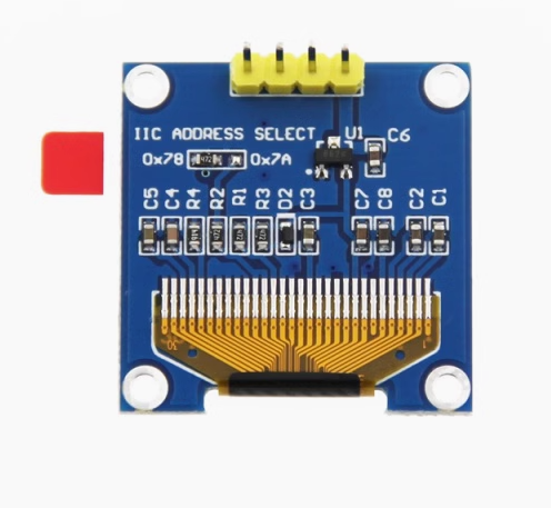
The 4-pin interface simplifies wiring significantly. The pins are clearly labeled on the back of the PCB.
I2C Pin Mapping on Common Boards:
Wiring Diagram:
OLED Module    →    Arduino Uno
─────────────────────────────
VCC           →    5V (or 3.3V)
GND           →    GND
SCL           →    A5 (SCL)
SDA           →    A4 (SDA)
Multiple I2C Devices: The I2C protocol supports multiple devices on the same bus as long as each has a unique address. The OLED’s default address is 0x3C (often configurable to 0x3D by soldering a resistor on the back) .
Usage Guide
Software Setup (Arduino IDE)
Step 1: Install Required Libraries
The two essential libraries for using this display are Adafruit GFX (graphics primitives) and Adafruit SSD1306 (hardware driver).
-
Open Arduino IDE → Sketch → Include Library → Manage Libraries
-
In the search bar, type “Adafruit SSD1306”
-
Click Install on the result by Adafruit
-
When prompted to install dependencies (including Adafruit GFX), click Install All
Step 2: Basic Test Code
Upload this sketch to verify your display is working.
#include <Wire.h>
#include <Adafruit_GFX.h>
#include <Adafruit_SSD1306.h>
#define SCREEN_WIDTH 128
#define SCREEN_HEIGHT 64
#define OLED_ADDR 0x3C
Adafruit_SSD1306 display(SCREEN_WIDTH, SCREEN_HEIGHT, &Wire, -1);
void setup() {
Serial.begin(9600);
if(!display.begin(SSD1306_SWITCHCAPVCC, OLED_ADDR)) {
Serial.println(F("SSD1306 allocation failed"));
for(;;);
}
display.clearDisplay();
display.setTextSize(2);
display.setTextColor(SSD1306_WHITE);
display.setCursor(0, 20);
display.println("Hello!");
display.println("OLED Ready");
display.display();
}
void loop() {
}
After uploading, the display should show “Hello!” and “OLED Ready” on a black background.
Troubleshooting Initialization Failures
If the display does not light up or remains blank:
-
Check Wiring: Verify VCC→5V/3.3V, GND→GND, SCL→A5, SDA→A4
-
Check I2C Address: Run an I2C scanner sketch to detect the actual address (usually 0x3C or 0x3D)
-
Modify Code: Update OLED_ADDR to match your detected address
-
Check Power: Ensure your power source can supply ~20mA
I2C Address Scanner Sketch
Use this to verify your display is detected and find its address:
#include <Wire.h>

void setup() {
  Wire.begin();
  Serial.begin(9600);
  Serial.println("I2C Scanner");
}

void loop() {
  byte error, address;
  int nDevices = 0;

  for(address = 1; address < 127; address++) {
    Wire.beginTransmission(address);
    error = Wire.endTransmission();

    if(error == 0) {
      Serial.print("I2C device found at address 0x");
      if(address < 16) Serial.print("0");
      Serial.println(address, HEX);
      nDevices++;
    }
  }

  if(nDevices == 0) Serial.println("No I2C devices found");
  delay(5000);
}
Displaying Basic Graphics
The Adafruit_GFX library provides a rich set of drawing functions:
display.clearDisplay();
display.drawPixel(10, 10, SSD1306_WHITE);
display.drawLine(0, 0, 127, 63, SSD1306_WHITE);
display.drawRect(10, 10, 50, 30, SSD1306_WHITE);
display.fillRect(70, 10, 40, 30, SSD1306_WHITE);
display.drawCircle(64, 32, 20, SSD1306_WHITE);
display.fillCircle(64, 32, 15, SSD1306_WHITE);
display.setTextSize(1);
display.setTextColor(SSD1306_WHITE);
display.setCursor(0, 55);
display.print("Graphics Demo");
display.display();
Displaying Bitmaps (Images)
You can convert images to C arrays using LCD Image Converter or similar tools. Here’s how to handle custom graphics:
const unsigned char myBitmap[] PROGMEM = {
};
display.clearDisplay();
display.drawBitmap(48, 16, myBitmap, 32, 32, SSD1306_WHITE);
display.display();
Power Management for Battery-Powered Projects
The OLED display’s power consumption is directly related to how many pixels are lit .
Power-Saving Best Practices :
-
Turn off display when not needed: Use display.ssd1306_command(SSD1306_DISPLAYOFF) followed by display.ssd1306_command(SSD1306_DISPLAYON) to wake
-
Avoid “burn-in” effects: While OLEDs have improved, displaying the same static image for thousands of hours may cause uneven pixel wear
-
Use deep sleep modes: For battery-powered projects, power down the display completely between updates
-
Dimming: The SSD1306 does not support hardware brightness control from user code (it is software-controlled)
Using with ESP32 / ESP8266
The same libraries work for ESP32 and ESP8266. The I2C pins vary by board:
ESP32:
-
SDA: GPIO21 (default I2C)
-
SCL: GPIO22 (default I2C)
-
Use Wire.begin() without parameters for default pins
ESP8266 (NodeMCU):
Using with Raspberry Pi (Python)
The display also works with Raspberry Pi using Python libraries:
import board
import busio
import adafruit_ssd1306
from PIL import Image, ImageDraw, ImageFont
i2c = busio.I2C(board.SCL, board.SDA)
oled = adafruit_ssd1306.SSD1306_I2C(128, 64, i2c)
oled.fill(0)
oled.text("Hello Pi!", 0, 0, 1)
oled.show()
Using with STM32 (STM32CubeIDE/HAL)
For STM32 developers, the I2C interface is enabled in STM32CubeMX :
-
Enable I2C1 in “Connectivity” section
-
Default settings (Standard Mode, 100 KHz, 7-bit address) work well
-
Generate code and use HAL_I2C_Mem_Write() for commands and data
Q: What is the difference between this OLED and a standard LCD?
OLED pixels emit their own light, so there’s no backlight. This provides true blacks (pixels are completely off), much higher contrast, and wider viewing angles. OLEDs also consume less power when displaying darker content. Traditional LCDs require a backlight that constantly draws power and can’t achieve true black.
Q: What is the difference between the 0.96" OLED and the 0.91" version?
The 0.96″ display offers 128×64 pixels (64 pixels tall), allowing 4 lines of standard text or more detailed graphics. The 0.91″ version is 128×32 pixels (32 pixels tall), supporting only 2 lines of text . For most projects, the 128×64 version provides greater flexibility.
Q: Does this display support grayscale or color?
No. This is a monochrome (single-color) OLED. Each pixel is either ON (blue) or OFF (black). No grayscale or color is available. However, dithering techniques can simulate varying intensities.
Q: How many characters can the display show?
With the default 8×8 pixel font, the display can show approximately 16 characters × 8 lines = 128 characters total. With larger fonts (e.g., 16×16), fewer characters fit. This is an advantage over the 0.91″ 128×32 display, which only supports about 2 lines of 16-characters each .
Q: Can two of these displays run on the same I2C bus?
Yes, but with limitations. Both would typically share the same address (0x3C). To run two displays, you need an I2C multiplexer (e.g., TCA9548A) or use one with a modified address (0x3D) if your board supports it .
Q: What is the lifespan of the OLED display?
OLEDs have a rated lifespan of approximately 20,000-30,000 hours of continuous operation. Uneven pixel wear (similar to “burn-in” on plasma TVs) can occur if static images are displayed for extremely long periods . Avoid leaving the same image on screen for thousands of hours.
Q: How much current does the display draw?
Power consumption depends on how many pixels are lit :
-
All pixels off (black screen): ~2mA – excellent for battery-powered projects in standby
-
Full screen white: ~20-25mA – maximum power draw
-
Displaying typical text/dashboard: ~10-15mA
Q: Can I adjust the display brightness?
The SSD1306 does not support hardware brightness control from user code (it requires modifying display registers). However, you can simulate dimming by displaying patterns with fewer pixels lit, or use a series resistor on the VCC line (not recommended for beginners). For practical purposes, most users do not adjust brightness.
Q: Why is my display flickering or showing artifacts?
Possible causes:
-
Insufficient power: Ensure your power supply can deliver ~30mA
-
Long wires: Keep I2C wires short (<30cm) to prevent signal integrity issues
-
Bus conflicts: Check that no other I2C device shares the same address
-
Library version: Update to the latest Adafruit libraries
Q: Can I use 5V logic with the display?
Yes, the module is 5V tolerant. The VCC pin can accept 3.3V or 5V power, and the SDA/SCL signals are also 5V compatible . The internal voltage regulator handles the conversion.
Q: Will an all-white screen damage the display?
No, but it will dramatically increase power consumption. Avoid leaving static patterns on screen for extremely extended periods (thousands of hours) as this may cause uneven pixel wear . For most hobbyist and intermittent use, this is not a concern.
Q: Which pins on the Arduino Uno should I connect to?
Connect SDA to A4 and SCL to A5. These are the dedicated I2C pins on Arduino Uno and Nano . For Mega 2560, use pins 20 (SDA) and 21 (SCL). For ESP32, use GPIO21 (SDA) and GPIO22 (SCL).
Q: Can I use the display with a Raspberry Pi?
Yes. The display works with Raspberry Pi using the Adafruit_CircuitPython_SSD1306 library. Connect SDA to GPIO2 (Pin 3) and SCL to GPIO3 (Pin 5). Power with 3.3V (Pin 1) or 5V (Pin 2). Voltage compatibility is not an issue as the module accepts either.
Q: What if my display has 7 pins instead of 4?
The 7-pin version supports both SPI and I2C communication, while the 4-pin is I2C only. If you have a 7-pin module, refer to its specific documentation for connection instructions. The 4-pin version discussed here is optimized for simplicity .
Q: What's the difference between the Adafruit and U8g2 libraries?
Both work well but have different strengths:
-
Adafruit_SSD1306: Simpler, better documentation, easier for beginners, excellent for basic text and simple graphics
-
U8g2: More features (more fonts, advanced graphics), but slightly steeper learning curve
For first-time users, start with Adafruit.
Q: Why is my code compiling but the display is blank?
Check these issues in order:
-
Power and connections – use a multimeter to verify 5V and GND
-
I2C address – run the I2C scanner to confirm the address (common values: 0x3C or 0x3D)
-
Display initialization – verify display.begin(SSD1306_SWITCHCAPVCC, address) is called before any drawing
-
Call display.display() – drawing functions write to a buffer; you must call display.display() to push the buffer to the screen
Q: Can I display custom fonts?
Yes. The Adafruit_GFX library supports custom fonts. Use the setFont() method after creating a custom font object. For more advanced typography, consider the U8g2 library, which includes dozens of pre-built fonts .
Q: Can I use this display with MicroPython?
Yes, the SSD1306 driver is included in the MicroPython framebuf module. Example from the official MicroPython documentation works with boards like ESP32, ESP8266, and Pyboard.
Q: What about using this with STM32? I2C seems complex.
STM32 works well. The initialization code is generated by STM32CubeMX (enable I2C1 in “Connectivity”) and uses the HAL HAL_I2C_Mem_Write() function to send commands and data. Third-party SSD1306 libraries are available for STM32, or you can write bare-metal I2C communication using HAL functions .