Product Overview
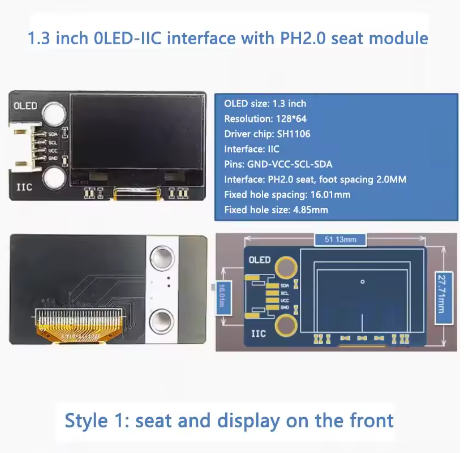
The 1.3-inch White OLED Display Module is a high-contrast, energy-efficient graphic display designed for embedded systems, IoT devices, and portable electronics . Powered by the SH1106 driver IC and featuring a crisp 128×64 pixel resolution, this larger-format display delivers bright white text, detailed graphics, and custom icons on a true black background.
OLED (Organic Light Emitting Diode) technology requires no backlight, as each pixel emits its own light. This self-emissive design provides true blacks (inactive pixels are completely off), an exceptional contrast ratio of 2000:1, and wide viewing angles over 160°—ensuring the display remains readable from virtually any angle .
The module features a convenient PH2.0 connector on the front, making it easy to connect using standard 4-pin JST cables. It uses the I2C (IIC) interface, requiring only two data lines (SDA and SCL) to connect to your microcontroller. This preserves valuable I/O pins for other sensors and peripherals .
With support for both 3.3V and 5V logic, it is directly compatible with Arduino, ESP32, ESP8266, STM32, and most other development boards – no level shifters required . The larger 1.3-inch active area offers noticeably more space for UI elements, dashboards, and menus than the 0.96-inch version while maintaining the same simple 4-wire I2C hookup .
Key Features
-
Larger 1.3-Inch Active Area: 29.42 × 14.7mm display area offers significantly more screen real estate than 0.96″ displays while maintaining 128×64 resolution
-
White Monochrome OLED: Clean white pixels on true black background provide excellent contrast and professional appearance
-
SH1106 Driver IC: Industry-standard controller with built-in 128×64-bit SRAM display buffer and support for I2C interface
-
PH2.0 Connector (Front-Mounted): Convenient JST connector on the front for easy plug-and-play installation using standard 4-pin cables
-
I2C Interface: 4-pin connection (VCC, GND, SCL, SDA) with default address 0x3C – requires only 2 data lines
-
Wide Voltage Compatibility: Operates on DC 3.3V – 5V, compatible with both 5V (Arduino) and 3.3V (ESP32/ESP8266) systems
-
Ultra-Low Power Consumption: ~20mA typical operating current (all pixels on), with no power consumed by unlit pixels – ideal for battery-powered projects
Technical Specifications
Pinout & Connection Guide
The module features a PH2.0 connector on the front with the following 4-pin configuration:
I2C Pin Mapping for Common Development Boards
Wiring Diagram (Arduino Uno)
OLED Module          →    Arduino Uno
─────────────────────────────────────
VCC                  →    5V
GND                  →    GND
SCL                  →    A5 (SCL)
SDA                  →    A4 (SDA)
PH2.0 Connector Information
The PH2.0 connector is a 2.0mm pitch JST-compatible connector commonly used for battery connections and display modules. The front-mounted connector allows for easy cable access and keeps the back side of your project clean for mounting .
SH1106 Driver Note
This 1.3″ display uses the SH1106 driver IC. The SH1106 has internal RAM of 132×64 pixels, while the visible area is 128×64 pixels. This is different from the SSD1306 driver found on some 0.96″ displays . For library compatibility:
-
Adafruit SH110X library and U8g2 library work with both SH1106 and SSD1306 – recommended
-
The SH1106 requires a column start address offset (handled automatically by modern libraries)
-
The onboard regulator accepts 3.3V or 5V, so this module works out-of-the-box with both 3.3V and 5V microcontrollers
Usage Guide
Software Setup (Arduino IDE)
Step 1: Install Required Libraries
The Adafruit SH110X library (with Adafruit GFX) is the most reliable choice for SH1106 displays, offering excellent support.
-
Open Arduino IDE → Sketch → Include Library → Manage Libraries
-
Search for and install:
Alternative Libraries:
Step 2: I2C Address Verification
Most modules use address 0x3C (some may use 0x3D depending on configuration) . Run this I2C scanner to verify:
#include <Wire.h>

void setup() {
  Wire.begin();
  Serial.begin(9600);
  Serial.println("I2C Scanner");
}

void loop() {
  byte error, address;
  int nDevices = 0;

  for(address = 1; address < 127; address++) {
    Wire.beginTransmission(address);
    error = Wire.endTransmission();

    if(error == 0) {
      Serial.print("I2C device found at address 0x");
      if(address < 16) Serial.print("0");
      Serial.println(address, HEX);
      nDevices++;
    }
  }

  if(nDevices == 0) Serial.println("No I2C devices found");
  delay(5000);
}
Step 3: Basic Test Sketch (Adafruit SH110X Library)
#include <Wire.h>
#include <Adafruit_GFX.h>
#include <Adafruit_SH110X.h>
#define SCREEN_WIDTH 128
#define SCREEN_HEIGHT 64
#define OLED_RESET -1
Adafruit_SH1106G display(SCREEN_WIDTH, SCREEN_HEIGHT, &Wire, OLED_RESET);
void setup() {
Serial.begin(9600);
if(!display.begin(0x3C, true)) {
Serial.println(F("SH1106 allocation failed"));
for(;;);
}
display.clearDisplay();
display.setTextSize(1);
display.setTextColor(SH110X_WHITE);
display.setCursor(0, 0);
display.println("1.3 OLED");
display.println("128x64");
display.println("SH1106 Ready!");
display.display();
}
void loop() {
}
Step 4: Alternative Using U8g2 Library
#include <Arduino.h>
#include <U8g2lib.h>
#include <Wire.h>
U8G2_SH1106_128X64_NONAME_F_HW_I2C u8g2(U8G2_R0, U8X8_PIN_NONE);
void setup() {
u8g2.begin();
u8g2.enableUTF8Print();
u8g2.setFont(u8g2_font_ncenB08_tr);
}
void loop() {
u8g2.firstPage();
do {
u8g2.drawStr(0, 15, "1.3 OLED");
u8g2.drawStr(0, 35, "128x64");
u8g2.drawStr(0, 55, "SH1106 - I2C");
} while ( u8g2.nextPage() );
delay(1000);
}
Raspberry Pi Setup (Python)
-
Enable I2C: sudo raspi-config → Interface Options → I2C → Yes
-
Install required libraries:
sudo apt-get install python3-pip
pip3 install luma.oled
-
Python example code:
from luma.core.interface.serial import i2c
from luma.oled.device import sh1106
from luma.core.render import canvas
serial = i2c(port=1, address=0x3C)
device = sh1106(serial, width=128, height=64)
with canvas(device) as draw:
draw.rectangle(device.bounding_box, outline="white", fill="black")
draw.text((10, 20), "1.3 OLED", fill="white")
draw.text((10, 40), "128x64 Ready!", fill="white")
ESP32 MicroPython Setup
from machine import Pin, I2C
import framebuf
from sh1106 import SH1106_I2C
i2c = I2C(0, scl=Pin(22), sda=Pin(21), freq=400000)
devices = i2c.scan()
print("Found I2C devices:", [hex(d) for d in devices])
oled = SH1106_I2C(128, 64, i2c, addr=0x3C)
oled.fill(0)
oled.text("1.3 OLED", 0, 0, 1)
oled.text("128x64", 0, 20, 1)
oled.text("SH1106 Ready!", 0, 40, 1)
oled.show()
Q: What is the difference between this 1.3" OLED and the 0.96" version?
The 1.3″ display has a larger active area (29.42mm × 14.7mm) while maintaining the same 128×64 resolution . This provides larger, more readable pixels and significantly more screen real estate – about 1.8 times the area of 0.96″ displays – making UI elements easier to see and interact with .
Q: What is the default I2C address of this display?
The default I2C address is 0x3C. Some modules may support 0x3D depending on the DC pin configuration . Use the I2C scanner sketch above to verify the address of your specific module .
Q: Can I use this display with a 5V Arduino Uno directly?
Yes. The module includes an onboard voltage regulator that accepts both 3.3V and 5V power. Connect VCC to 5V, GND to GND, SCL to A5, and SDA to A4 – no level shifters required .
Q: Why does my display stay blank after power-up?
Check these common issues:
-
Wrong I2C address – Run the I2C scanner sketch (should be 0x3C or 0x3D)
-
Wiring – Re-verify VCC, GND, SCL, SDA connections
-
Missing initialization code – Ensure your setup function initializes the display properly
-
Library selection – Make sure you’re using a library that supports SH1106
-
Power supply – Ensure your power source can deliver adequate current (max ~40mA)
Q: How do I use this display with an ESP32 or ESP8266?
Yes. Both ESP32 and ESP8266 use 3.3V logic, which is directly compatible. Connect VCC to 3.3V, GND to GND, and SCL/SDA to the appropriate I2C pins: ESP32: GPIO21(SDA)/GPIO22(SCL); ESP8266: GPIO4(SDA)/GPIO5(SCL). The same Adafruit SH110X and U8g2 libraries work on these platforms .
Q: What is the PH2.0 connector and why is it convenient?
The PH2.0 connector is a 2.0mm pitch JST-compatible connector. The front-mounted connector allows you to use standard 4-pin JST cables for plug-and-play installation without soldering. This makes prototyping and wiring much faster and more reliable .
Q: Can I display Chinese characters or custom fonts?
Yes. The U8g2 library supports UTF-8 encoding and includes various fonts including Chinese (u8g2_font_wqy12_t). Enable with u8g2.enableUTF8Print() and use the appropriate font. For custom fonts, use tools like LCD Image Converter to convert text into bitmap data arrays.
Q: What is the lifespan of the OLED display?
OLEDs have a rated lifespan of approximately 50,000 hours of continuous operation (about 5.7 years) . Avoid displaying static images for extremely long periods to prevent uneven pixel wear (“burn-in”). For typical intermittent hobbyist use, this is not a concern.
Q: Why does the SH1106 driver require specific library support?
The SH1106 has internal RAM of 132×64 pixels, while the visible area is 128×64 pixels. It requires a column start address of 0x02 (unlike SSD1306’s 0x00) . Libraries like Adafruit SH110X and U8g2 handle this offset automatically, ensuring proper display alignment.
Q: Can I use the 1.3" OLED for battery-powered projects?
Yes. OLEDs are power-efficient because only lit pixels consume power. The module typically draws ~20mA with all pixels on . When displaying dark or partially lit screens, power consumption drops significantly. For maximum battery life, implement sleep modes to turn off the display when not actively in use (send command 0xAE to the display).