Product Overview
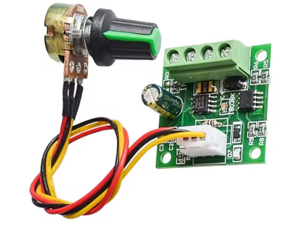
The 1803BW PWM DC Motor Speed Controller is a compact and versatile speed regulation module designed for low-voltage DC motor applications. Based on the ubiquitous NE555 timer IC , this controller uses advanced Pulse Width Modulation (PWM) technology to provide smooth, stepless speed adjustment from 0% to 100% duty cycle .
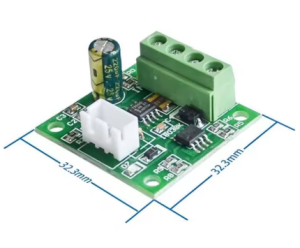
What sets this controller apart is its ability to operate at ultra-low voltages starting from just 1.8V , making it ideal for battery-powered projects, small robotics, and applications where power sources are limited . Despite its tiny footprint (approximately 32mm x 32mm), it can handle continuous currents up to 2A and deliver up to 30W of power to your motor .
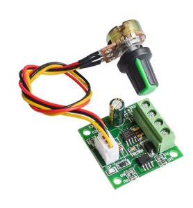
The 1803BW features a built-in potentiometer with an integrated on/off switch, allowing you to control both power and speed from a single knob . A self-resetting fuse provides overload protection—if the current exceeds 2A, the fuse automatically disconnects and restores itself once the fault is cleared and the module cools down .
This controller is the ideal choice for a vast array of low-voltage applications, including:
-
Battery-powered toys and hobby projects
-
Small robotics and educational kits
-
3V, 5V, 6V, and 12V DC fan speed control
-
Aquarium oxygen pump regulation
-
LED dimming (with appropriate load considerations)
-
Micro DC motor speed adjustment in models and dioramas
Key Features
-
Ultra-Wide Low Voltage Operation: Accepts DC input from 1.8V to 12V , making it compatible with single-cell batteries (1.5V AA), 3V, 5V, 6V, 9V, and standard 12V systems .
-
2A High Current Capacity: Capable of handling continuous output currents up to 2A (maximum output power 30W) , suitable for a wide range of small to medium DC motors .
-
NE555 PWM Control: Built around the classic and reliable NE555 timer IC, generating stable PWM signals for precise motor speed regulation .
-
Integrated Potentiometer with Switch: Features a rotary potentiometer that combines on/off control and stepless speed adjustment in a single knob . Simply turn the knob to power on and increase speed; turn it fully counter-clockwise to switch off .
-
Self-Resetting Fuse Protection: Includes a 2A resettable fuse (PTC) that automatically disconnects the circuit during overload or short-circuit conditions. Once the fault is removed and the module cools, the fuse resets itself—no replacement needed .
-
Power-On Indicator LED: An onboard LED provides clear visual confirmation when power is applied to the module .
-
0%-100% Duty Cycle Adjustment: Allows full range speed control from completely stopped to maximum speed, with excellent low-speed torque characteristics .
-
Compact and Lightweight: Tiny PCB footprint (approx. 32mm x 32mm x 14mm) and low weight (approx. 5g) allow for easy integration into space-constrained projects .
-
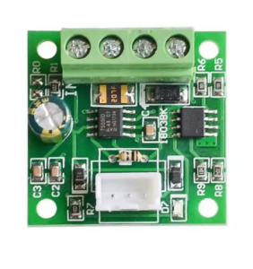
Easy 3-Terminal Wiring: Simple screw terminal connections for power input (VIN/GND) and motor output (OUT/GND) make installation quick and error-free .
-
Wide Application Compatibility: Perfect for DC motors, fans, pumps, and other low-voltage DC loads requiring speed regulation .
Technical Specifications
Pinout & Interface Guide
The 1803BW controller features three clearly labeled screw terminals for all connections.
Power Terminals
-
VIN / + (Power Input): Connect your DC power source (1.8V-12V) here. Observe correct polarity (+ to +, – to -). The module accepts a wide range of power sources including batteries, DC power supplies, and USB power banks (with appropriate voltage) .
-
GND / – (Power Ground): Connect to the negative terminal (ground) of your DC power source.
Motor Terminals
Control Interface
Status Indicators
Usage Guide
Important Safety Warnings
-
DC ONLY: This controller is designed strictly for DC circuits. Never connect it to AC mains power (e.g., 110V or 220V AC). Doing so will instantly destroy the controller and poses a serious fire hazard .
-
Voltage Limits: Do not exceed the maximum input voltage of 12V DC. Applying more than 15V can permanently damage the module .
-
Current Limits: The module is rated for 2A continuous current. Do not exceed this rating. The self-resetting fuse will trip during overload, but repeated overloading may degrade the module .
-
Motor Type: This controller is for brushed DC motors only . It is NOT compatible with brushless DC motors (BLDC), stepper motors, or AC motors.
-
High-Current Motors: Despite the 2A rating, this controller is not suitable for motors requiring sustained currents above 0.5A, such as large 775 motors or children’s ride-on car motors, as the small PCB has limited heat dissipation .
Wiring Guide
Step-by-Step Operation
-
Mount the Controller: Secure the module in your project enclosure using mounting tape or by creating a mounting hole for the potentiometer shaft.
-
Connect the Motor: Connect your DC motor to the OUT + and OUT – terminals.
-
Connect the Power Supply: Connect your DC power source (battery or power supply) to the VIN + and GND – terminals. Ensure the power supply is turned OFF or disconnected during wiring .
-
Set Initial Speed: Turn the potentiometer knob fully counter-clockwise to its OFF position.
-
Apply Power: Turn on your DC power source or connect your battery. The motor should remain off.
-
Adjust Speed: Slowly turn the potentiometer knob clockwise. You will feel a slight click as the switch engages, and the motor will begin to spin. Continue turning clockwise to increase speed.
-
Stop the Motor: Turn the knob fully counter-clockwise until you feel the click. This disconnects power to the motor.
-
Change Direction (if needed): To reverse the motor’s direction, turn off the power, swap the two motor wires at the OUT + and OUT – terminals, and then reapply power.
Q: What types of motors can I use with the 1803BW controller?
This controller is designed for brushed DC motors only operating at 1.8V to 12V . It is ideal for small motors found in toys, hobby projects, fans, and pumps. It is not suitable for brushless motors (BLDC), stepper motors, or AC motors.
Q: What is the difference between this 1803BW and other PWM controllers?
The 1803BW is distinguished by its ultra-low voltage operation starting at just 1.8V , making it ideal for single-cell battery applications. It also features an integrated on/off switch in the potentiometer, combining power and speed control in one knob .
Q: Can I use this controller with a single AA battery?
Yes. A single AA battery provides approximately 1.5V, which is within the 1.8V-12V operating range (very close to the minimum). For reliable operation with a single cell, ensure your motor is rated for 1.5V operation and draws less than 2A.
Q: Can I use this controller to change the direction of my motor?
This model provides speed control only. It does not have a direction switch. However, you can easily change the motor’s direction by swapping the two motor wires at the OUT + and OUT – terminals . Always turn the power off before doing this.
Q: What power supply should I use?
Use a DC power source with a voltage between 1.8V and 12V that matches your motor’s rating. The power source must be capable of delivering at least the current your motor will draw (up to 2A). Examples include:
-
1.5V AA batteries
-
3.7V LiPo batteries
-
5V USB power banks
-
6V battery packs
-
9V batteries
-
12V DC power supplies
Q: The product description says "cannot drive motors larger than 0.5A continuous current." Why?
This is an important clarification. While the module is rated for 2A peak current and has a 2A fuse, the small PCB has limited heat dissipation capability. For continuous, reliable operation, it’s recommended to stay under 0.5A to 1A . Motors that continuously draw 2A (like large 775 motors) will overheat the module. The 2A rating is for surge currents and short-duration loads.
Q: The controller gets warm. Is this normal?
Some warmth is normal when switching currents near 1A. However, if it becomes too hot to touch, you are likely exceeding the recommended continuous current rating. Reduce the load or ensure adequate ventilation.
Q: What is the self-resetting fuse and how does it work?
The self-resetting fuse (PTC) is a protection device. If the current exceeds 2A (due to a motor stall or short circuit), the fuse heats up and “trips,” breaking the circuit to protect the module . Once the fault is removed and the module cools down, the fuse automatically resets and normal operation can resume.
Q: The controller doesn't work. The motor doesn't move.
Follow this checklist:
-
Check Power: Verify with a multimeter that you have the correct DC voltage at the VIN + and GND – terminals (1.8V-12V).
-
Check Knob Position: Ensure the knob is turned clockwise past the initial “click” to turn the power ON .
-
Check Fuse: If you recently experienced an overload, the self-resetting fuse may be tripped. Turn off power, allow the module to cool for a few minutes, and try again .
-
Check Connections: Ensure all wires are securely fastened in the screw terminals.
-
Test the Motor: Connect your motor directly to the power source (briefly) to ensure it works.
Q: The motor runs at full speed all the time, and the knob doesn't control it.
This indicates that the PWM control circuit may have failed. This can happen if the module was overloaded or experienced a short circuit. You will likely need to replace the controller.
Q: The motor runs in the wrong direction.
This is easily fixed. Turn off the power, swap the two motor wires at the OUT + and OUT – terminals, and then reapply power .
Q: Can I use this controller to dim LEDs?
With caution. This is a PWM controller, which can be used for dimming single-color LEDs. However:
-
Ensure the LED voltage matches your power supply voltage .
-
Ensure the total LED current does not exceed 2A .
-
This will not work with RGB or addressable LED strips.
Q: Does the potentiometer have an off position?
Yes. The potentiometer has an integrated switch. Turning the knob fully counter-clockwise until you feel a click will completely disconnect power to the motor