Product Overview
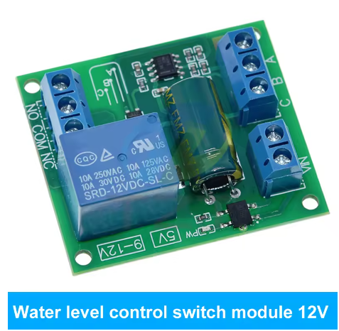
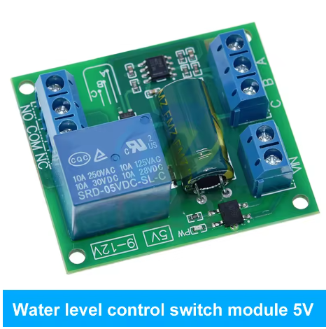
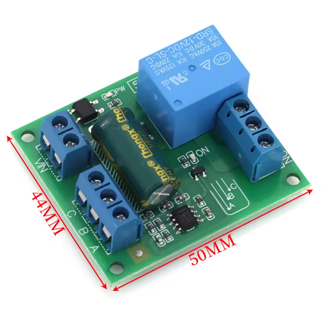
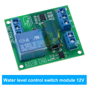
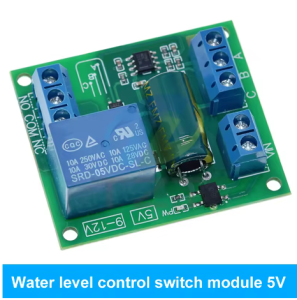
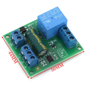
The 12V NE555 Automatic Water Level Controller Module is a smart, self-contained electronic control board designed to automate water tank filling and pump control operations. Built around the industry-standard NE555 timer IC from Texas Instruments – one of the most reliable integrated circuits in electronics history – this module provides a cost-effective, maintenance-free solution for preventing tank overflows and pump dry-running .
The controller continuously monitors water levels in both overhead (upper) and ground (lower) tanks using simple electrode probes . When the water level in the overhead tank falls below a preset low level, the module automatically turns the pump ON. When the water reaches the preset high level, the module turns the pump OFF, preventing spillage and waste .
What sets this module apart is its dual-tank monitoring capability and dry-run protection. A dedicated sensor in the lower (source) tank ensures that if the water level there falls below a safe minimum, the controller overrides all other commands and shuts the pump OFF immediately . This protects your pump from running dry, which can cause overheating and permanent damage.
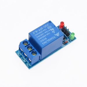
The module is designed to work with 12V DC power, making it compatible with automotive systems, 12V battery banks, and standard 12V wall adapters. The relay output can control pumps, solenoid valves, or other electrical loads up to 250V AC at 10A or 30V DC at 10A .
Key Features
-
Automatic Fill Control: Monitors water levels in overhead tanks using three electrode probes (low, high, common). Pumps water when low, stops when high .
-
Dual-Tank Monitoring: Simultaneously monitors both the overhead (destination) tank and the ground (source) tank for complete system control.
-
Dry-Run Protection: A dedicated low-water sensor in the source tank prevents the pump from running when water is insufficient, protecting the pump from damage .
-
NE555-Based Bistable Control: Utilizes the industry-standard NE555 timer IC configured as an RS flip-flop – no microcontroller programming required .
-
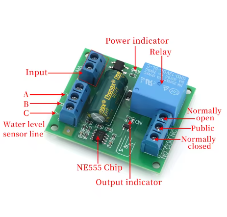
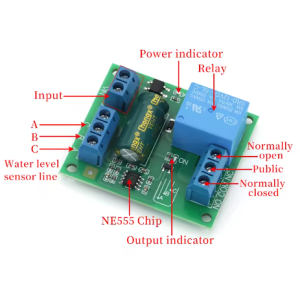
Simple Electrode Sensing: Uses stainless steel probes for the overhead tank (A=High, B=Low, C=Common) and lower tank (D=Low, E=Common) .
-
Manual Override Capability: Includes push-button switches for manual pump start (SW1) and stop (SW2) .
-
LED Status Indicators: Power indicator and pump status LED for easy monitoring of system state.
-
Relay Output: Built-in relay rated for 250V AC at 10A or 30V DC at 10A, capable of directly controlling pumps up to 1 HP .
-
12V DC Operation: Low-voltage control side keeps electronics safe; the relay isolates the high-voltage pump circuit.
-
Debounced Sensing: Includes filter capacitors to prevent false triggering due to water turbulence or electrical noise .
Technical Specifications
Pinout & Interface Guide
Sensor Probe Connections
Power & Output Connections
System Wiring Diagram
┌─────────────────────────────────────────────────────────────────┐
│                     UPPER TANK                                  │
│                         │                                       │
│    ┌────────────────────┼────────────────────┐                  │
│    │                    │                    │                  │
│    ▼                    ▼                    ▼                  │
│   [A] High            [B] Low              [C] Common           │
│    │                    │                    │                  │
│    └────────────────────┼────────────────────┘                  │
│                         │                                       │
│                      (to module)                                │
└─────────────────────────────────────────────────────────────────┘
                              │
┌─────────────────────────────────────────────────────────────────┐
│                     LOWER (SOURCE) TANK                         │
│                         │                                       │
│              ┌──────────┼──────────┐                            │
│              ▼          ▼          ▼                            │
│             [D]       [E]                                     │
│           (Low)     (Common)                                  │
│              │          │                                      │
│              └──────────┘                                      │
│                         │                                       │
│                      (to module)                                │
└─────────────────────────────────────────────────────────────────┘
Usage Guide
Operating Principle
The NE555 timer IC is configured as a bistable flip-flop (RS latch) with its threshold (pin 6) and trigger (pin 2) inputs connected to the upper tank probes A (high) and B (low), respectively . Water is conductive, so when the level reaches a probe, that pin is pulled low, triggering a state change.
-
Normal State (Tank Empty): Initially, the overhead tank is empty. Electrode B is connected to ground through a resistor, and with no water contact, the potential at pin 2 is drawn towards ground. This triggers the lower comparator, causing the flip-flop to go low and the output at pin 3 to go high . This energizes the relay through transistor T2, and the pump starts operating.
-
Tank Filling: The pump runs until water reaches probe A (high level). Current flows from the reference rod C to A via a resistor to ground. Since the resistance between rod C and A is lower, the potential at pin 6 reaches nearly the supply voltage . This triggers the upper comparator, causing the flip-flop to go to a high state, and the output at pin 3 goes low. The relay de-energizes, and the pump switches off .
-
Tank Emptying: This condition continues until the water level in the overhead tank falls below the lower reference rod B, when again a pulse at pin 2 re-energizes the relay and restarts the pump .
Dry-Run Protection
The lower tank sensing circuit monitors the level in the source tank via probes D and E. When the lower tank water level falls below probe D, transistor T1 turns off, and the flip-flop gets a negative potential through pin 4 (reset), immediately resetting the flip-flop to a high state . The output at pin 3 is forced low, de-energizing the relay and switching off the pump regardless of the upper tank’s state . This ensures the pump never runs dry.
Manual Controls
Probe Installation Guidelines
-
Use Stainless Steel Probes: For long-term reliability, use stainless steel rods. Ordinary copper or iron probes will corrode over time. Two closely spaced (about 10mm apart) stainless-steel bolts may be used as sensors .
-
Probe Spacing: Mount probes about 10mm apart to ensure reliable water contact without bridging.
-
Common Probe (C): Place the common probe at the bottom of the tank, below the lowest level .
-
Low Probe (B): Position this probe at the minimum desired water level (where pump should start) .
-
High Probe (A): Position this probe at the maximum desired water level (where pump should stop) .
-
Lower Tank Probe (D): Position this probe at the minimum safe water level in the source tank. Below this, the pump will be disabled to prevent dry running.
Electrical Connections
-
Power: Connect a 12V DC power supply to VCC and GND (use a 12V 1A adapter minimum) .
-
Probes: Connect the five probe wires to the corresponding terminals. For interconnection, use any low-voltage twin-wire/cable with a length of 30 to 90 meters .
-
Pump: Connect the pump power cable through the relay contacts:
-
230V AC pump: Live → COM, Pump Live → NO, Neutral direct to supply
-
12V/24V DC pump: Positive supply → COM, Pump positive → NO, negative direct to supply
Note: For pumps up to 1 HP, a 30A relay is recommended for reliable operation .
Q: Why is dry-run protection important?
Submersible pumps and many water pumps rely on water for cooling. Running without water causes overheating and rapid wear, leading to pump failure and expensive repairs. This module prevents that by monitoring the source tank level and automatically cutting power when water is insufficient .
Q: What type of probes should I use for long-term installation?
Use stainless steel rods or bolts. Ordinary copper or galvanized probes will corrode in water, leading to false readings and eventual failure. Stainless steel is highly resistant to corrosion and will last for years .
Q: Can the probe cables be extended for long distances?
Yes, the circuit includes a potentiometer (VR1) that can be adjusted to compensate for cable resistance, especially useful when the controller is located far from the tanks (up to 30-90 meters of cable) .
Q: What is the purpose of the capacitors in the circuit?
Capacitors C1 and C2 provide debouncing and noise filtering. When water is turbulent or there are electrical transients on the power line, the probes may get false contact signals. The capacitors smooth these out, preventing the pump from cycling on and off rapidly .
Q: Can the pump be started manually even if the tank is full?
Yes, pressing SW1 (manual start) will override the automatic control and start the pump. Use this for testing or when you need extra water beyond the preset high level. Press SW2 to stop manually .
Q: How does this module compare to a microcontroller-based controller?
The NE555 solution is purely hardware-based, requiring no programming and having no risk of firmware bugs or crashes. It’s simple, robust, and ideal for applications where reliability is critical. Microcontroller solutions offer more flexibility (e.g., display, timers) but require programming knowledge and are more complex.
Q: What happens if the probes are not fully submerged but in contact with splash?
The debouncing capacitors help filter out brief contacts. However, for reliable operation, the probes should be installed in a stilling well or at a location where they will be fully submerged when the water level reaches them.
Q: Can this module be used for a drainage (sump pump) application?
The circuit is designed for filling (overhead tank) control . For drainage (sump pump) applications, you would need to modify the logic or use a different configuration of the NE555. The standard circuit fills the tank when low and stops when high – the opposite of sump pump operation.
Q: What power supply is recommended for this module?
A 12V, 1A DC supply from any transformer-based or SMPS power supply can be used for powering the entire circuit . For system stability, a regulated 12V supply is recommended.
Q: Can this controller handle a 1 HP pump?
Yes. With a 30A relay (as recommended in some designs), this controller can easily handle pumps up to 1 HP . Always check your pump’s current rating and select an appropriately rated relay. For pumps above 1 HP, use an external contactor.