Description
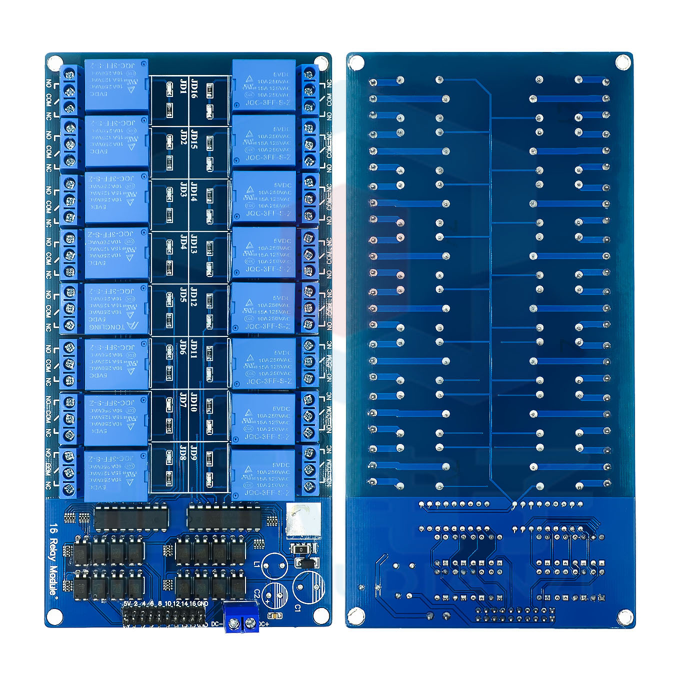
The 16-Channel Relay Module 5V is a high-capacity, industrial-grade control board designed for projects and systems requiring reliable switching of up to sixteen independent high-power loads. Unlike basic relay modules, this board features optocoupler isolation on every channel, providing complete electrical separation between your microcontroller (Arduino, Raspberry Pi, ESP32, STM32, etc.) and the high-voltage load side — protecting sensitive electronics from voltage spikes and noise.
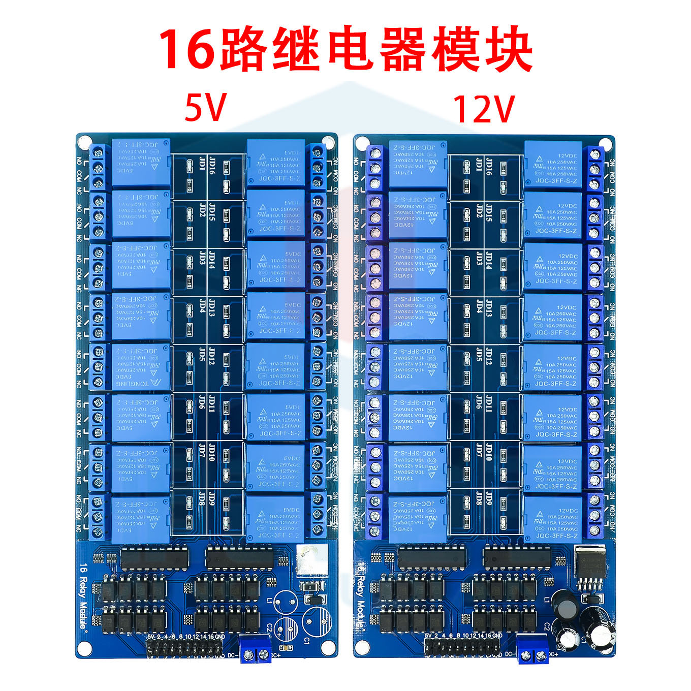
A key differentiator of this module is the onboard LM2596 DC-DC step-down power supply, which allows you to power the entire relay bank from a wide input voltage range (typically 6V–35V DC) while delivering a stable 5V to the relay coils and optocoupler circuits. This eliminates the need for a separate 5V power supply, even when all 16 relays are activated simultaneously.
Each relay includes a visible LED status indicator, and the module is designed for easy integration into 19″ racks, control panels, or DIY enclosures. Whether you are building a home automation hub, an industrial PLC expansion, or a test equipment controller, this 16-channel relay module delivers professional-grade performance and safety.
Features
-
16 independent relays with optocoupler isolation per channel
-
Onboard LM2596 switching power supply (6V–35V DC input → stable 5V output)
-
Eliminates external 5V power supply — runs from a single higher-voltage source
-
Active HIGH trigger (standard 5V TTL logic compatible)
-
LED indicators for each relay channel
-
Screw terminals for all high-voltage connections
-
Standard 2.54mm pin header for control signals
-
Optocoupler protection for microcontroller I/O pins
-
Suitable for AC (250V/10A) and DC (30V/10A) loads
Technical Parameters
Usage Guide
1. Powering the Module
The onboard LM2596 regulator allows flexible power input:
Connect your DC power supply to the VIN and GND terminals (not the 5V pin). The module will generate stable 5V internally.
2. Connecting to a Microcontroller (e.g., Arduino)
⚠️ The module’s VCC pin is an output (5V from LM2596). Do not connect an external 5V source to it.
3. AC/DC Load Wiring
Each relay has three screw terminals:
-
COM (Common) – Connect to live/positive supply
-
NO (Normally Open) – Connect to load’s live/positive input
-
NC (Normally Closed) – Unused or alternate circuit
Example (AC lamp control):
AC Live ──→ COM
AC Neutral ──→ Lamp Neutral
Lamp Live ──→ NO
4. Sample Arduino Code
int relayPins[16] = {2,3,4,5,6,7,8,9,10,11,12,13,14,15,16,17};
void setup() {
for (int i = 0; i < 16; i++) {
pinMode(relayPins[i], OUTPUT);
digitalWrite(relayPins[i], LOW);
}
}
void loop() {
digitalWrite(relayPins[0], HIGH);
delay(2000);
digitalWrite(relayPins[0], LOW);
delay(2000);
for (int i = 0; i < 16; i++) {
digitalWrite(relayPins[i], HIGH);
delay(500);
}
delay(1000);
for (int i = 15; i >= 0; i--) {
digitalWrite(relayPins[i], LOW);
delay(500);
}
}
5. LM2596 Output Voltage Adjustment (If Needed)
The LM2596 is preset to 5V. If adjustment is required:
-
Locate the small potentiometer on the LM2596 board
-
Turn very slowly while measuring the output at the 5V pin
-
Do not exceed 5.5V — relay coils may overheat
Most users never need to adjust this.
6. Important Notes
-
Always connect the module GND to your microcontroller GND for signal reference.
-
For 16 relays all active simultaneously, ensure your input power supply can deliver at least 1.5A at the input voltage.
-
The optocoupler isolation protects your microcontroller, but the load side still requires proper fusing and safety enclosures.
Q: What is the advantage of having an LM2596 power supply on board?
Without the LM2596, a 16-channel relay module would require an external 5V power supply capable of delivering ~1A (when all relays are on). The LM2596 allows you to use a single higher-voltage supply (12V–24V, common in industrial settings) and step it down to clean 5V onboard — simplifying wiring and reducing component count.
Q: Can I still use an external 5V supply if I prefer?
Yes, but you must remove or bypass the LM2596 output (consult the board schematic). The default configuration expects power at VIN. Connecting an external 5V supply to the 5V pin while the LM2596 is active may cause damage.
Q: What is the purpose of optocoupler isolation?
Optocouplers use light to transmit the control signal, creating no electrical connection between your microcontroller and the relay coils/loads. This protects your expensive controller from:
-
Back EMF from inductive loads (motors, solenoids)
-
Voltage spikes from AC mains switching
-
Ground loop noise in industrial environments
Q: How much current does the module draw from the input supply?
-
Idle (all relays OFF) : ~30–50mA
-
One relay ON : ~70–80mA
-
All 16 relays ON : ~1.0A – 1.2A at 5V equivalent → at 12V input, ~500mA; at 24V input, ~250mA (plus LM2596 efficiency losses)
Recommend an input power supply rated at least 12V / 1A for full 16-channel operation.
Q: Can I use this module with a 3.3V microcontroller (ESP32, Raspberry Pi Pico)?
Yes, but not directly. The module expects 5V logic signals. For 3.3V systems, use a logic level shifter (bidirectional, 3.3V→5V) between your microcontroller and the IN1–IN16 pins. Alternatively, use an external transistor buffer board.
Q: Is this module suitable for controlling 16 independent AC appliances?
Absolutely. Each relay is fully independent. You can mix AC and DC loads, different voltages, and different currents across channels, as long as each stays within 10A / 250V AC or 30V DC.
Q: What happens if I supply more than 35V to VIN?
The LM2596 has a maximum input rating of 40V absolute, but 35V is the safe continuous limit. Exceeding this may destroy the regulator and potentially send overvoltage to the relay coils.
Q: Can I use this module for business / industrial automation?
Yes, this is one of our most popular modules for professional use, including:
-
PLC expansion for 24V industrial control systems
-
Automated test equipment (ATE)
-
Building management systems (lighting, HVAC, blinds)
-
Agricultural automation (irrigation, greenhouse fans)
-
Smart home hubs (professional installations)
-
Machinery retrofitting
The combination of optocoupler isolation, onboard power regulation, and 16 channels makes it a cost-effective alternative to industrial relay banks.
Q: How do I know if the optocoupler is working correctly?
When the control signal is applied, the relay clicks and the LED lights. The optocoupler’s function is transparent to the user — if the relay responds correctly and your microcontroller remains protected, the optocoupler is functioning. For testing, you can measure zero continuity between the input pin and the relay coil circuit.
Q: Can I mount this module in a standard 19" rack?
The board dimensions (approx. 200mm × 110mm) fit within many 19″ rack shelves or DIN rail adapters. We offer optional mounting brackets and DIN rail clips (sold separately). Contact us for custom panel mounting solutions.
Q: What is the lifespan of the relays on this module?
Mechanical relays are rated for approximately 100,000 – 1,000,000 switching cycles depending on load current. For applications requiring very frequent switching (e.g., >10 times per minute), consider our SSR (Solid State Relay) modules instead.
Q: Does the LM2596 generate heat? Do I need cooling?
The LM2596 is a switching regulator (efficient, ~80-90%). For typical 12V input and 8-10 relays active, heat is minimal. For 35V input and all 16 relays continuously active, the regulator may become warm — ensure adequate airflow or mount with the metal tab exposed to air.