Product Overview
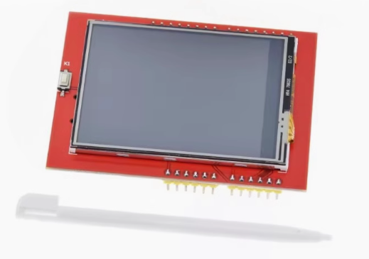
The 2.4 Inch TFT LCD Touch Screen Module is a high-performance color display designed to bring vibrant graphical interfaces to your microcontroller projects. Powered by the popular ILI9341 driver IC, this module delivers a crisp 320×240 pixel resolution with 65K true colors (RGB 565) , providing rich, vivid visuals for everything from sensor dashboards to interactive menus.
This “unified driver” version is engineered for broad compatibility, supporting both 8-bit parallel and 4-wire SPI interfaces. The SPI mode requires only 5 I/O pins, saving valuable microcontroller resources while maintaining excellent performance. The included resistive touchscreen overlay (controlled by the XPT2046 IC) and touch pen enable intuitive user interaction, making it ideal for handheld devices, data loggers, and industrial control panels.
An onboard microSD card slot provides convenient expandable storage for images, fonts, and data logging – perfect for photo viewers or data acquisition systems. Whether you’re an Arduino hobbyist or developing commercial embedded products, this module offers a reliable, feature-rich display solution supported by extensive library resources.
Key Features
-
ILI9341 Driver IC: Industry-standard controller with onboard RAM buffering, reducing microcontroller workload for smooth graphics performance
-
320×240 Pixel Resolution: QVGA resolution with 65K/262K RGB color depth for crisp text and detailed graphics
-
Flexible Interface Options: Supports both 8-bit parallel (fastest) and 4-wire SPI (fewer pins) communication modes
-
Resistive Touchscreen: 4-wire resistive touch panel with XPT2046 controller; includes stylus pen for precise input calibration
-
Onboard MicroSD Card Slot: Convenient expandable storage for images, fonts, and data logging via SPI interface
-
Wide Voltage Compatibility: Operates with 3.3V – 5V power; onboard 3.3V regulator and level-shifted logic (5V tolerant)
-
Adjustable Backlight: 4 white LEDs with PWM brightness control via dedicated LED pin
-
Broad Compatibility: Works with Arduino Uno, Mega 2560, Leonardo, ESP32, STM32, and Raspberry Pi (with appropriate wiring)
-
Military-Grade Reliability: Manufactured to long-term stable operation standards, suitable for demanding environments
-
Extensive Library Support: Compatible with Adafruit_GFX, Adafruit_ILI9341, TFT_eSPI, and MCUFRIEND_kbv libraries
Technical Specifications
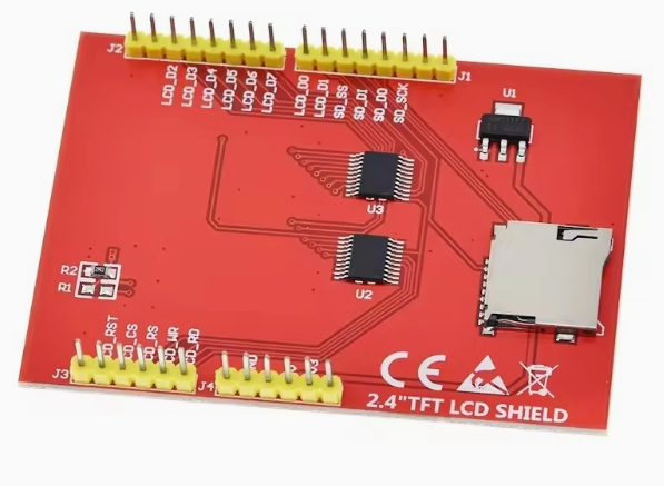
Pinout & Interface Guide
This module is available in two common formats: breakout board (with pin headers) and Arduino shield (direct stack). The breakout version’s pin assignments may vary by manufacturer.
Breakout Board Pins (SPI Mode – Common Configuration)
Arduino Shield Pin Mapping
When used as a shield for Arduino Uno/Mega:
⚠️ Important Verification: Pin assignments can vary between manufacturers. Always check the silkscreen on the back of your specific module.
⚠️ Warning for Mega 2560 Users: SPI pins differ from Uno. For breakout modules, use ICSP header pins (SCK=52, MOSI=51, MISO=50).
Usage Guide
Hardware Setup
Breakout Board (SPI Mode – Recommended)
-
Power: Connect VCC to 5V (or 3.3V) on your microcontroller; GND to common ground
-
SPI Connections: Connect CS, DC, MOSI, SCK to digital pins per configuration
-
Touch Connections: Connect T_CS, T_DIN, T_DO, T_CLK to SPI bus with dedicated CS
-
Backlight: Connect LED pin to 3.3V (on) or PWM pin for brightness control
-
Optional: Insert microSD card (FAT16/FAT32 formatted) into the module’s slot
Arduino Shield (Direct Stack)
-
Power off Arduino – disconnect USB cable
-
Align shield headers with Arduino’s female pins; press firmly to seat
-
Verify no bent pins underneath shield before powering on
-
Connect USB to Arduino – shield draws power from 5V pin
Software Installation (Arduino IDE)
Install Required Libraries
Open Arduino IDE → Sketch → Include Library → Manage Libraries. Search and install:
-
Adafruit GFX Library – Core graphics primitives
-
Adafruit ILI9341 Library – Hardware-specific driver (SPI mode)
-
XPT2046_Touchscreen (by Paul Stoffregen) – Touch controller support (optional)
Basic Test Sketch (SPI Mode)
#include <Adafruit_GFX.h>
#include <Adafruit_ILI9341.h>
#include <SPI.h>
#define TFT_CS 10
#define TFT_DC 9
#define TFT_RST 8
#define TFT_LED 12
Adafruit_ILI9341 tft = Adafruit_ILI9341(TFT_CS, TFT_DC, TFT_RST);
void setup() {
Serial.begin(9600);
tft.begin();
tft.setRotation(1);
tft.fillScreen(ILI9341_BLACK);
pinMode(TFT_LED, OUTPUT);
digitalWrite(TFT_LED, HIGH);
tft.fillRect(50, 50, 200, 100, ILI9341_RED);
tft.setCursor(80, 95);
tft.setTextColor(ILI9341_WHITE);
tft.setTextSize(2);
tft.print("ILI9341 Ready!");
Serial.println("Display initialized");
}
void loop() {
}
Touchscreen Calibration
Resistive touch requires calibration for accurate coordinate mapping:
-
Upload touch calibration sketch (provided in XPT2046_Touchscreen library)
-
Press corners as prompted
-
Record raw ADC min/max values (range approximately 150–900)
-
Map values using:
int x = map(raw_x, TS_MINX, TS_MAXX, 0, tft.width());
int y = map(raw_y, TS_MINY, TS_MAXY, 0, tft.height());
Q: What is the difference between ILI9341 and other TFT drivers (ST7789, ILI9325)?
The ILI9341 is the industry standard for 2.4″ QVGA displays, offering both 8-bit parallel and 4-wire SPI interfaces. It includes onboard RAM buffering, reducing microcontroller workload significantly. Unlike older ILI9325 (parallel-only) or newer ST7789 (SPI-optimized), the ILI9341 provides a versatile balance of speed and pin efficiency.
Q: Can I use this with ESP32 or Raspberry Pi?
Yes. For ESP32, connect to 3.3V logic and use same SPI pins (adjust library configuration). For Raspberry Pi, you’ll need manual wiring (breakout) or SPI configuration; the standard shield format does not fit physically.
Q: What is the "unified driver" meaning?
The module supports multiple interface modes (8-bit parallel, 4-wire SPI). This flexibility allows you to choose between fastest speed (parallel) or minimal pin usage (SPI), making it compatible with virtually any microcontroller.
Q: How many pins are required to use this display in SPI mode?
SPI mode requires 5 pins: VCC, GND, CS, DC, MOSI, SCK (touch requires additional CS; SD card requires dedicated CS). Total ~8-10 pins for full functionality with touch and SD card.
Q: What does the "Unified Driver" mean for shield users?
The shield version uses the 8-bit parallel interface (D0-D7 pins) by default, which provides maximum speed but uses ~16 pins. The “unified” driver refers to the ILI9341’s ability to handle either mode, not the shield’s physical interface.
Q: Why does my screen stay white after power-on?
White backlight with no graphics typically indicates:
-
Power is connected but SPI initialization failed
-
Library mismatch or incorrect pin assignments
-
Loose connections or bent header pins
-
Verify tft.begin() (ILI9341) not tft.init() (which is for other drivers)
Q: Can I use the touchscreen without the XPT2046 library?
Yes, you can read analog values directly from the touch pins (YP, XM, YM, XP). However, the XPT2046 library simplifies calibration and provides pressure (z-axis) detection.
Q: What is the maximum SPI communication speed?
The ILI9341 supports up to 60Mbps display communication; touch controller operates reliably up to 5Mbps. For Arduino, 8-16MHz is typical; ESP32 can utilize higher speeds (up to 40MHz) with proper configuration.
Q: How much current does the display consume?
Without backlight, display draws ~10-20mA. With full backlight brightness, total approaches 120-150mA. Use external power for portable projects or PWM dimming to save battery.
Q: What is the expected backlight lifespan?
Rated for over 30,000 hours continuous operation (approximately 3.5 years)
Q: The display works but colors are inverted (blue/red swapped).
This indicates RGB vs BGR color format mismatch. In Adafruit library, try adding tft.invertDisplay(true) or swap byte order in library configuration.
Q: Touch coordinates are inverted (X/Y swapped or reversed).
Resistive touch orientation is independent from display orientation. Calibrate axis mapping: swap TS_MINX/TS_MAXX if axis reversed; exchange map(x) and map(y) if X/Y swapped.
Q: Can I use this module with Arduino Leonardo or Mega 2560?
Yes for Mega (spacing fits), but SPI pins differ from Uno. Use ICSP header pins (SCK=52, MOSI=51, MISO=50). For Leonardo, the shield may not fit physically; use breakout version instead.
Q: SD card and touch not working simultaneously.
Both share SPI bus. Ensure each device has dedicated CS (chip select) pin and that your code sets HIGH on the other device’s CS before switching. This prevents bus conflicts.
Q: What can I build with this 2.4" ILI9341 module?
Popular projects include:
-
Portable Oscilloscope: Real-time waveform display with touch controls
-
Weather Station: Graphical dashboard with sensor data logging to SD card
-
Handheld Game Console: Retro gaming with buttons or touch interface
-
Industrial HMI: Control panel for CNC machines or 3D printers
-
Battery Monitor: Real-time voltage/current graph and capacity tracking
-
Photo Viewer: Load bitmap images from SD card
Q: Where can I find more code examples and libraries?
Start with manufacturer’s wiki page (Elecrow, Waveshare, or your vendor) for matching sample code. The Adafruit ILI9341, TFT_eSPI, and MCUFRIEND_kbv libraries provide extensive examples.