Description
The 2-Channel Relay Module without Optocoupler with LED 3.3V is a cost-effective, compact dual-relay switching solution designed for low-voltage control applications where optical isolation is not required. Operating on a 3.3V DC supply—ideal for Raspberry Pi, ESP32, ESP8266, STM32, and other 3.3V logic microcontrollers—this module allows you to independently control two high-power AC or DC loads using simple logic signals from your development board.
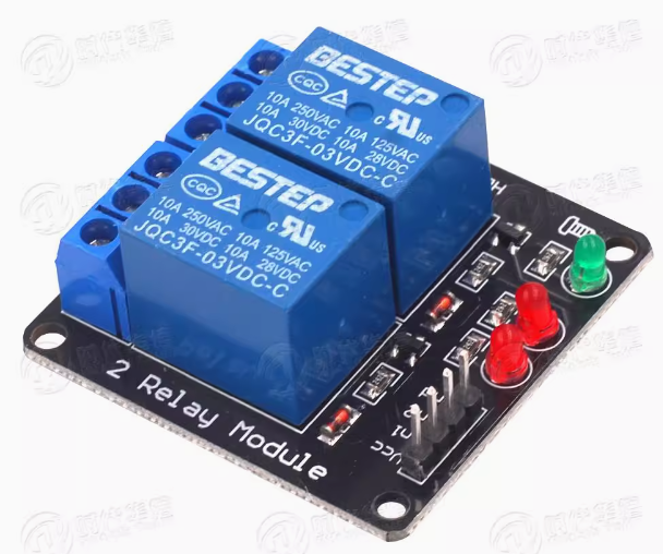
Unlike optocoupler-isolated relay modules, this version features a direct transistor-driven circuit design. This eliminates the optocoupler components, resulting in a lower-cost module that is perfectly suitable for non-critical applications, educational projects, and prototyping environments where electrical isolation between the control side and load side is not a primary safety concern. The module retains essential features including dual LED indicators for each channel to show relay activation status, and a power indicator LED for visual confirmation of module operation.
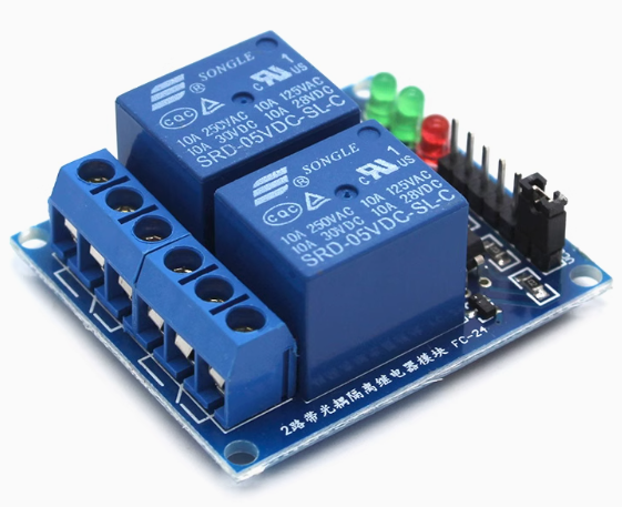
Each of the two independent channels features a Single-Pole Double-Throw (SPDT) relay rated for 10A at 250V AC or 10A at 30V DC, making it capable of controlling a wide range of devices including lights, fans, pumps, solenoids, motors, and household appliances. The module includes screw terminal blocks for reliable load connections and a 4-pin male header (2.54mm pitch) for easy connection to your microcontroller.
The module typically offers jumper-selectable high-level or low-level trigger modes, allowing you to configure the activation behavior without modifying your code. This flexibility makes it compatible with both active-high and active-low control systems.
Note on Design Difference: Unlike optically isolated relay modules, this version does not provide galvanic isolation between the low-voltage control circuit and the high-voltage load circuit. The control ground (GND) and load circuit ground are electrically connected through the transistor driver stage. For applications requiring complete electrical isolation (e.g., controlling household AC mains from sensitive electronics), please consider our optically isolated relay module series. This module is best suited for low-voltage DC load control, educational use, and non-critical switching applications.
Whether you need to control LED lighting strips, automate a small greenhouse, manage 12V pumps, or create a simple home automation prototype, this 2-channel 3.3V relay module delivers reliable, budget-friendly switching performance in a compact package.
Key Features
-
3.3V DC Operation – Specifically designed for 3.3V logic microcontrollers including Raspberry Pi, ESP32, ESP8266, STM32, and others .
-
Dual Independent Channels – Two SPDT relays allow simultaneous control of two separate loads with individual trigger inputs .
-
Direct Transistor Driver – No optocoupler isolation; lower cost design suitable for non-critical applications and low-voltage DC loads.
-
Configurable Trigger Logic – Jumper-selectable High-Level Trigger (active HIGH) or Low-Level Trigger (active LOW) operation .
-
10A High-Current Relays – Each relay rated for 10A at 250V AC or 10A at 30V DC .
-
SPDT Contact Configuration – Each relay provides Normally Open (NO), Normally Closed (NC), and Common (COM) terminals for flexible wiring .
-
LED Status Indicators – Individual red LEDs illuminate when each relay is activated; green power LED shows module status .
-
Wide Compatibility – Works directly with 3.3V logic level microcontrollers without level shifters .
-
Screw Terminal Connections – Heavy-duty screw terminal blocks for reliable load wiring and easy installation.
-
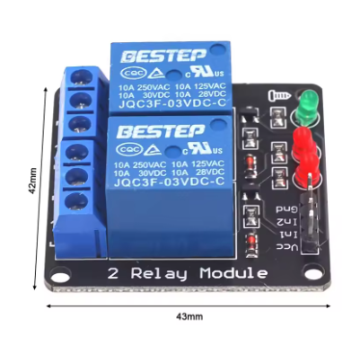
Compact Form Factor – Small footprint (approx. 50mm x 40mm x 18mm) with mounting holes for secure installation .
Technical Parameters
Usage Guide
Important Note on Non-Isolated Design
This module does not include optocoupler isolation. The control circuit ground (GND) is electrically connected to the relay driver circuit. When controlling AC mains voltages, there is no galvanic isolation between your microcontroller and the high-voltage circuit. For safety:
-
Do NOT use this module to directly control household AC mains (110V/220V) unless your microcontroller and all connected equipment are properly enclosed and isolated from user contact.
-
This module is best suited for low-voltage DC applications (e.g., 12V LED strips, 24V DC motors, 5V pumps) where isolation is not critical.
-
For AC mains control, we strongly recommend using an optically isolated relay module to protect your microcontroller and ensure user safety.
How It Works
The module uses a transistor driver circuit to control each relay. When the trigger input (IN1 or IN2) receives the appropriate signal (HIGH or LOW depending on jumper configuration), the transistor turns on, allowing current to flow through the relay coil. The energized relay switches the common (COM) terminal connection from the normally closed (NC) contact to the normally open (NO) contact, completing the circuit to your load.
Wiring Instructions
Step 1 – Control Side Connection (to Microcontroller)
Connect the 4-pin male header (2.54mm pitch) as follows:
Step 2 – Load Side Connection (to Device)
Each relay channel has a 3-pin screw terminal block:
Wiring Example – Controlling a 12V DC LED Strip (Recommended Use):
-
Connect 12V DC power supply positive → COM terminal
-
Connect LED strip positive → NO terminal
-
Connect LED strip negative → 12V power supply negative directly
-
When relay activates, the circuit closes and the LED strip turns ON
⚠️ Safety Warning: This module does not provide optocoupler isolation. When controlling any voltage above 30V DC or AC mains, ensure all connections are properly insulated and the entire system is enclosed. Do not touch any wiring while power is applied.
Trigger Mode Configuration (High/Low Level Jumper)
The module features jumper-selectable trigger modes for each channel (typically labeled S1 and S2 or a single H/L jumper block) .
Recommended Settings by Microcontroller:
To change trigger mode:
-
Locate the jumper(s) on the PCB (small black plastic caps covering header pins)
-
Gently remove the jumper cap
-
Reposition it over the desired pins (refer to silkscreen labels: LOW/GND or HIGH/VCC)
-
Some modules have separate jumpers for each channel; others use a single jumper for both channels
Arduino Sample Code (Low-Level Trigger Configuration)
Since this module operates at 3.3V, you can use it with 3.3V boards (ESP32, Raspberry Pi Pico, etc.) directly. For 5V Arduino boards, use a level shifter on the signal lines, or set the jumper to HIGH mode and verify compatibility.
const int RELAY1 = 2;
const int RELAY2 = 3;
void setup() {
pinMode(RELAY1, OUTPUT);
pinMode(RELAY2, OUTPUT);
digitalWrite(RELAY1, HIGH);
digitalWrite(RELAY2, HIGH);
}
void loop() {
digitalWrite(RELAY1, LOW);
delay(2000);
digitalWrite(RELAY1, HIGH);
delay(1000);
digitalWrite(RELAY2, LOW);
delay(2000);
digitalWrite(RELAY2, HIGH);
delay(1000);
}
Raspberry Pi (Python) Sample Code
import RPi.GPIO as GPIO
import time
GPIO.setmode(GPIO.BCM)
RELAY1 = 17
RELAY2 = 18
GPIO.setup(RELAY1, GPIO.OUT)
GPIO.setup(RELAY2, GPIO.OUT)
GPIO.output(RELAY1, GPIO.HIGH)
GPIO.output(RELAY2, GPIO.HIGH)
try:
while True:
GPIO.output(RELAY1, GPIO.LOW)
print("Relay 1 ON")
time.sleep(2)
GPIO.output(RELAY1, GPIO.HIGH)
print("Relay 1 OFF")
time.sleep(1)
GPIO.output(RELAY2, GPIO.LOW)
print("Relay 2 ON")
time.sleep(2)
GPIO.output(RELAY2, GPIO.HIGH)
print("Relay 2 OFF")
time.sleep(1)
except KeyboardInterrupt:
GPIO.cleanup()
Installation Tips
-
Mounting: Secure the module using the mounting holes with M3 screws or double-sided tape.
-
Ventilation: Allow adequate airflow around the module, especially when switching high currents continuously.
-
Wire Gauge: Use 14-22 AWG wire for load connections depending on current. For 10A loads, minimum 18 AWG copper wire is recommended.
-
Enclosure: For permanent installations, mount the module inside an enclosure, especially when controlling higher voltages.
Important Safety Note
This module lacks optocoupler isolation. For controlling household AC mains (110V/220V) , we strongly recommend using an optically isolated relay module instead to protect your microcontroller and ensure user safety. This non-isolated version is best suited for:
-
Low-voltage DC loads (12V, 24V)
-
Educational and prototyping environments
-
Non-critical switching applications
-
Projects where control and load share a common ground
Q: What is the difference between this module and an optocoupler-isolated relay module?
This module is designed for low-voltage DC applications where complete electrical isolation is not required .
Q: Can I use this module with a 5V Arduino?
The module is designed for 3.3V logic. For 5V Arduino boards:
-
Option 1: Use a logic level shifter (bidirectional) between Arduino outputs and module inputs
-
Option 2: Set trigger jumper to HIGH mode and test – some modules accept 5V inputs, but this may exceed specifications
-
Option 3: Use our 5V version of this relay module for direct compatibility
Applying 5V directly to a 3.3V-rated input may damage the module.
Q: Can I use this module to control household AC mains (110V/220V)?
Not recommended. This module does not provide optocoupler isolation, meaning there is no galvanic separation between your low-voltage microcontroller and the high-voltage AC circuit. For AC mains control, please use an optically isolated relay module for safety . This non-isolated version is best suited for low-voltage DC applications (12V-24V).
Q: What is the difference between High-Level Trigger and Low-Level Trigger?
The module includes jumpers to select the trigger mode per channel .
Q: Why does my relay click but the load does not turn on?
Possible causes:
-
Incorrect trigger mode: Check jumper settings (HIGH vs LOW) match your code
-
Wiring error: Verify COM and NO/NC connections
-
Load exceeds rating: Check if your load current exceeds 10A
-
Power supply insufficient: Ensure the 3.3V supply can provide sufficient current (up to 160mA when both relays active)
-
Common ground missing: Ensure microcontroller GND is connected to module GND
Q: What types of loads can I control with this relay?
The 10A relay can control:
-
AC loads (up to 250V) : Lights, fans, pumps, solenoid valves (with caution – isolation recommended)
-
DC loads (up to 30V) : LED strips, DC motors, automotive accessories, pumps
For inductive loads (motors, solenoids), consider adding an external flyback diode to protect relay contacts from voltage spikes.
Q: Can I use this module for both home and business applications?
Home users (low-voltage) : 3.3V microcontroller projects, LED strip control, aquarium pump automation, greenhouse misting systems, DIY robotics, model train control.
Business users (low-voltage) : Educational lab equipment, prototyping workstations, low-voltage test fixtures, battery management systems, small DC motor control.
For AC mains applications in business settings, please use optically isolated relay modules.
Q: How much current does each input pin draw?
Each trigger input draws approximately 5mA to 20mA when activated . Most 3.3V microcontrollers can drive this directly. For multiple channels simultaneously, ensure your microcontroller’s total output current does not exceed its rating.
Q: What is the lifespan of the relay contacts?
Mechanical relay contacts are rated for approximately 100,000 electrical operations at rated load or 10,000,000 mechanical operations (no load). For applications requiring millions of cycles, consider solid-state relays (SSRs) instead.
Q: Why doesn't my Raspberry Pi trigger the relay?
Common issue: Raspberry Pi GPIO pins output 3.3V logic. For this module, set the trigger jumper to LOW position (Active LOW) and use GPIO.output(pin, GPIO.LOW) to activate the relay . Also ensure:
-
The module is powered by a stable 3.3V supply (not from Pi GPIO pins alone)
-
Common ground between Pi GND and module GND
-
Jumper is correctly positioned