4-Channel ADS1115 16-Bit High-Precision ADC Module – Compact Analog-to-Digital Converter Development Board

SKU: FA2176
ADC Resolution

16-bit

Input Channels

4 (single-ended) / 2 (differential)

Sampling Rate

8 SPS – 860 SPS (programmable)

PGA Input Ranges

±0.256V, ±0.512V, ±1.024V, ±2.048V, ±4.096V, ±6.144V

Operating Voltage

2.0V – 5.5V DC

Current Consumption

150µA (continuous conversion mode)

I²C Interface

Up to 400 kHz; four pin-selectable addresses

Operating Temperature

-40°C to +125°C

Description

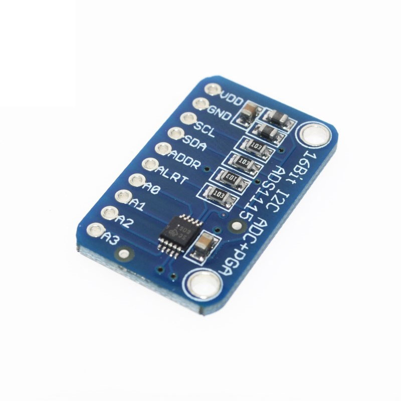
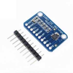
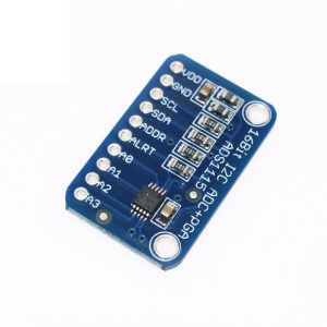
The 4-Channel ADS1115 Module is a high-precision, 16-bit analog-to-digital converter (ADC) breakout board designed to add accurate analog measurement capabilities to microcontrollers that lack analog inputs (such as the ESP8266) or require higher resolution than the built-in 10-bit ADCs found on most Arduino boards. At its heart lies the ADS1115 integrated circuit from Texas Instruments, a low-power, I²C-compatible, 16-bit delta-sigma ADC that delivers exceptional precision for sensor measurement applications .

Unlike standard microcontroller ADCs that offer only 10-bit resolution (1024 steps), the ADS1115 provides 16-bit resolution (65536 steps) , enabling detection of voltage changes as small as 0.1875mV when using the ±4.096V range. This level of precision is essential for measuring small-signal sensors like load cells, thermocouples, current sensors, and pressure transducers.

The module features a 4-channel input multiplexer (MUX) that can be configured for four single-ended inputs (measuring four separate signals relative to ground) or two differential inputs (measuring the voltage difference between two channels). The onboard Programmable Gain Amplifier (PGA) offers selectable input ranges from ±256mV to ±6.144V, allowing direct measurement of both tiny sensor signals and larger voltages without external signal conditioning .

Communication is handled via the I²C bus with four pin-selectable addresses (0x48, 0x49, 0x4A, 0x4B), allowing up to four modules to be connected on the same bus for a total of 16 analog inputs. The ADS1115 also features an integrated low-drift voltage reference, internal oscillator, and a programmable digital comparator for over/under-voltage detection .

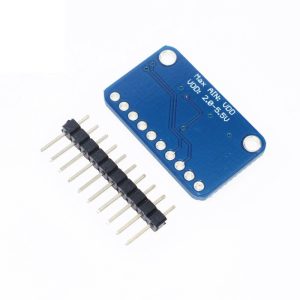
The module operates on a wide supply voltage range of 2.0V to 5.5V and consumes only 150µA in continuous conversion mode, making it ideal for battery-powered IoT devices, portable instrumentation, and remote sensor nodes .

Whether you are building a precision data logger, a battery monitoring system, a weigh scale, or any application requiring accurate analog measurement, the ADS1115 module delivers professional-grade performance in a compact, easy-to-use package.

Key Features

  • True 16-Bit Resolution – 65536 steps provide exceptional measurement precision for small-signal sensors 

  • 4-Channel Input Multiplexer – Configurable as four single-ended inputs or two differential inputs 

  • Programmable Gain Amplifier (PGA) – Selectable input ranges from ±256mV to ±6.144V for direct measurement of diverse signal levels 

  • Low Power Consumption – Only 150µA in continuous conversion mode; ideal for battery-powered applications 

  • Wide Operating Voltage – 2.0V to 5.5V supply range compatible with 3.3V and 5V systems 

  • Programmable Data Rate – 8 SPS to 860 SPS, allowing optimization between speed and noise performance 

  • I²C Interface – Simple two-wire communication with four pin-selectable addresses (up to 4 modules on same bus) 

  • Internal Low-Drift Voltage Reference – Stable measurements without external reference components 

  • Internal Oscillator – No external clock source required for operation 

  • Programmable Digital Comparator – Configurable for over-voltage, under-voltage, or window detection with ALERT/RDY output pin 

  • Single-Cycle Settling – Each conversion is stable without waiting for filter settling 

  • Wide Operating Temperature – -40°C to +125°C, suitable for industrial and automotive applications 

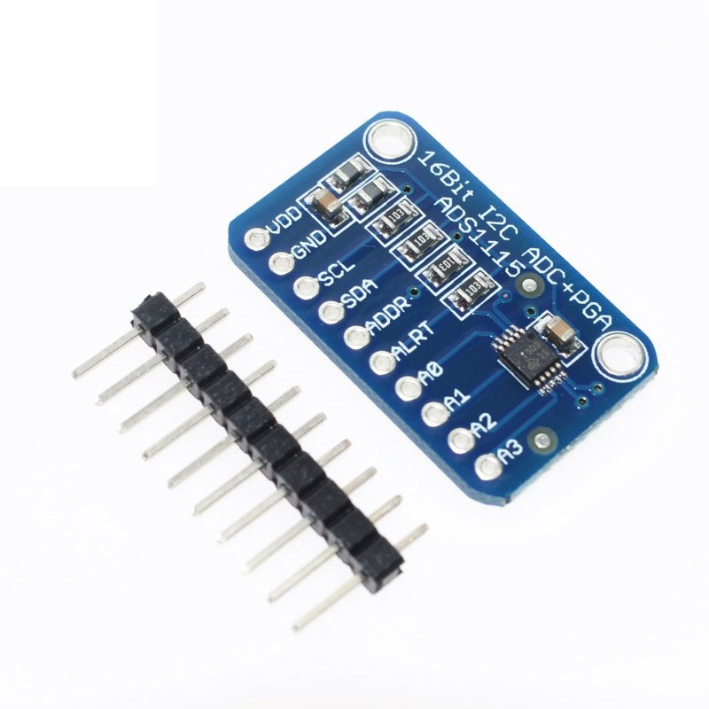
  • Compact Module Size – Small footprint with 0.1″ pin headers for breadboard and PCB integration

Technical Specifications 

Specification Value
ADC Resolution 16-bit
Input Channels 4 (single-ended) / 2 (differential) 
Sampling Rate 8 SPS – 860 SPS (programmable) 
PGA Input Ranges ±0.256V, ±0.512V, ±1.024V, ±2.048V, ±4.096V, ±6.144V 
Operating Voltage 2.0V – 5.5V DC 
Current Consumption 150µA (continuous conversion mode) 
I²C Interface Up to 400 kHz; four pin-selectable addresses 
Operating Temperature -40°C to +125°C 
Module Dimensions Approx. 25mm × 19mm (varies by manufacturer)
Interface 6-pin header (VDD, GND, SCL, SDA, ADDR, ALERT)

Typical Usage

  • Precision Sensor Measurement – Load cells, thermocouples, RTDs, pressure sensors, gas sensors, and humidity sensors

  • Battery Monitoring Systems – Measure battery voltage, charge/discharge current, and cell balancing in Li-ion/LiFePO4 packs

  • Portable Instrumentation – Handheld multimeters, data loggers, and field measurement devices

  • IoT Sensor Nodes – Add high-precision analog measurement to ESP8266/ESP32-based wireless sensors

  • Weigh Scales & Force Measurement – Precision weight sensing with strain gauge load cells

  • Current Sensing – Measure shunt voltage for current monitoring in power supplies and motor controls

  • Temperature Monitoring – Precision thermocouple and RTD measurements for industrial and laboratory applications

  • Medical Devices – Low-power, high-precision measurements for portable medical instruments

  • Solar Power Systems – Monitor panel voltage, battery voltage, and current from current sensors

  • Automotive Sensors – Measure MAP sensor, throttle position sensor, and other analog automotive sensors (12V systems require voltage dividers)

  • Data Acquisition Systems (DAQ) – Multi-channel precision measurement for laboratory and industrial data logging

  • Over/Under Voltage Protection – Use the programmable comparator for autonomous threshold detection without microcontroller intervention

Q: What is the difference between single-ended and differential measurement?

Single-ended measures the voltage on a channel relative to ground (GND). This is suitable for sensors that output a voltage relative to ground. Differential measures the voltage difference between two channels (e.g., A0 and A1), which is ideal for measuring signals with common-mode noise (like thermocouples) or sensors with floating outputs. The ADS1115 supports up to 4 single-ended channels or 2 differential channels .

Q: Why should I use this instead of my microcontroller's built-in ADC?

Most microcontrollers (Arduino Uno, ESP8266, etc.) have 10-bit ADCs (1024 steps), limiting precision. The ADS1115 offers 16-bit resolution (65536 steps) , enabling detection of voltage changes as small as 0.1875mV in the ±4.096V range. Additionally, the ADS1115 provides a programmable gain amplifier, internal voltage reference, and better noise performance than most built-in microcontroller ADCs .

Q: What is the maximum voltage I can measure with this module?

The maximum input voltage relative to GND is determined by the supply voltage (VDD). With VDD = 5V, the absolute maximum input voltage is VDD + 0.3V (5.3V). However, the PGA’s maximum input range is ±6.144V. For voltages above VDD, external voltage dividers must be used to scale down the input voltage to within the safe range.

Q: How do I change the I²C address?

The ADS1115 has four selectable addresses determined by the ADDR pin connection :

  • ADDR to GND → Address 0x48 (default)

  • ADDR to VDD → Address 0x49

  • ADDR to SDA → Address 0x4A

  • ADDR to SCL → Address 0x4B

This allows up to 4 modules on the same I²C bus (16 total analog inputs).

Q: What is the sampling rate and how does it affect readings?

The data rate is programmable from 8 to 860 samples per second (SPS) Higher rates provide faster measurements but higher noise. Lower rates provide lower noise and better resolution for slowly changing signals. For most sensor applications, 16-128 SPS works well. The 860 SPS setting is useful for capturing transient events.

Q: What is the ALERT/RDY pin used for?

The ALERT/RDY pin has two functions :

  • Comparator mode: Asserts when conversion data exceeds programmed high/low thresholds (over/under voltage detection)

  • Conversion ready mode: Asserts when a new conversion is complete, signaling the microcontroller to read the result

This pin can be used to trigger interrupts, reducing the need for continuous polling.

Q: Can I use this module with ESP8266 or ESP32?

Yes. The ESP8266 and ESP32 have only one analog input (ESP8266) or no true analog inputs (depending on the board). The ADS1115 adds up to 4 high-precision analog channels via I²C, making it ideal for IoT sensor projects. The module works at both 3.3V and 5V power levels, but note that the ADS1115’s maximum input voltage is VDD. If powering from 3.3V, inputs cannot exceed 3.3V.

Q: How do I read multiple channels?

To read multiple channels, you must reconfigure the MUX between readings. Write to the Config Register to select the next channel, wait for the conversion to complete (based on data rate), then read the result. Some users have reported channel swapping issues if readings are taken too quickly without proper delays between channel changes . The recommended approach is to check the conversion-ready status (via ALERT pin or status register) before reading.

Q: What is the PGA and why is it important?

The Programmable Gain Amplifier (PGA) amplifies small input signals before conversion, effectively increasing resolution for small signals . For example, with the ±0.256V range, a 16-bit reading represents approximately 7.8µV per step. The PGA allows measuring tiny sensor signals (thermocouples, strain gauges) without external amplification. Available ranges are ±0.256V, ±0.512V, ±1.024V, ±2.048V, ±4.096V, and ±6.144V .

Q: How do I measure voltages higher than 5V?

Use an external voltage divider to scale the voltage down to within the ADS1115’s input range. For example, to measure a 12V car battery with a maximum voltage of 14.4V: Use a divider ratio of approximately 1:4 (e.g., 10kΩ and 2.2kΩ) to scale 14.4V down to ~2.6V. Use precision resistors (0.1% or better) for accuracy, and consider using a voltage follower (op-amp) to buffer the divider output. The ADS1115’s 16-bit resolution will preserve measurement precision after scaling.