Product Overview
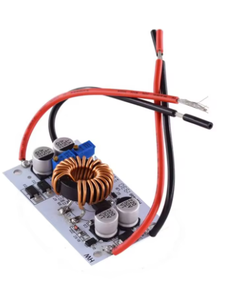
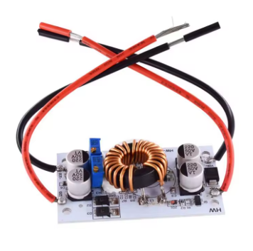
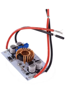
The 500W 10A DC-DC Boost Converter Module is a high-power, high-efficiency step-up switching regulator designed to convert lower DC voltages into higher, adjustable output voltages. Whether you need to power a laptop from a 12V car battery, drive high-power LED arrays, create a custom benchtop power supply, or charge lithium battery packs, this module delivers the performance and flexibility required for demanding applications .
At its core, this module utilizes a non-isolated boost (BOOST) topology with a maximum input current of 15A and a maximum output power of up to 500W. The input voltage range of 8.5V to 48V allows it to accept power from a wide variety of sources, including 12V car batteries, 24V truck electrical systems, solar panels, and 36V industrial power rails. The output is continuously adjustable from 10V to 50V, making it suitable for everything from charging lithium battery packs to powering 36V LED lighting systems .
A standout feature of this module is its dual-mode operation: it functions as both a constant voltage (CV) power supply and a constant current (CC) LED driver. The onboard potentiometers allow you to independently set the output voltage and current limit, making it perfect for charging batteries (where a constant current/constant voltage profile is required) and driving high-power LEDs (where a regulated current is essential to prevent thermal runaway) .
The module achieves a conversion efficiency of up to 96% thanks to its 150kHz switching frequency and high-quality components. For enhanced durability, the module is built on an aluminum PCB substrate, which acts as a heatsink to dissipate heat during high-power operation. When running at currents above 8-10A, external cooling (a fan or larger heatsink) is strongly recommended to maintain optimal performance and longevity .
Key Features
-
High Power Output: Capable of delivering up to 500W of output power with a maximum input current of 15A (output current up to 10A, derate based on input/output voltage differential) .
-
Wide Input & Output Range: Accepts DC input from 8.5V to 48V and provides an adjustable output from 10V to 50V .
-
Constant Voltage (CV) + Constant Current (CC) Mode: Functions as both a standard voltage regulator and a constant current LED driver. Ideal for charging batteries (CV/CC profile) and driving high-power LEDs .
-
High Conversion Efficiency: Achieves up to 96% efficiency, minimizing power loss and heat generation. Operating frequency: 150kHz .
-
Adjustable Output via Potentiometers: Multi-turn potentiometers allow for precise, independent adjustment of output voltage and constant current limit .
-
Built-in Protection Features: Includes overcurrent protection (OCP) and input reverse polarity protection to safeguard the module and your connected devices .
-
Robust Construction: Built on an aluminum PCB substrate for enhanced heat dissipation. Includes 4 mounting holes (3mm) for secure installation .
-
Parallel Operation Capability: Two modules can be connected in parallel to increase output current (e.g., two modules each set to 5A for a total of 10A) .
-
Compact Form Factor: Small footprint (approx. 70mm × 42mm × 13mm) and lightweight (approx. 50g) allows for easy integration into portable projects .
Technical Specifications
Pinout & Interface Guide
Input Side (Power Source)
-
IN+ (VIN): Connect to the positive terminal of your DC power source (e.g., 12V battery, 24V power supply).
-
IN- (GND): Connect to the negative terminal (ground) of your DC power source.
Output Side (Load Connection)
-
OUT+ (VOUT): Connect to the positive terminal of your load (LED array, battery, device).
-
OUT- (GND): Connect to the negative terminal (ground) of your load.
User Controls
Heat Dissipation
Usage Guide
Wiring Instructions
IMPORTANT: Always disconnect the input power source before wiring or modifying connections. Double-check polarity to avoid damage .
Basic Connection (CV Mode – Powering a Device)
-
Connect Input: Connect the positive wire of your DC power source (e.g., 12V battery) to the IN+ terminal. Connect the negative wire to the IN- terminal.
-
Set Initial Voltage: Before connecting your load, turn the voltage potentiometer fully counter-clockwise (minimum voltage). Turn the current potentiometer fully clockwise (maximum current limit).
-
Power On & Adjust Voltage: Apply power. Use a multimeter on the output terminals. Slowly turn the voltage potentiometer clockwise until you reach your desired output voltage (e.g., 19V for a laptop).
-
Connect Load: Turn off power, connect your device to OUT+ and OUT-, and re-apply power.
Constant Current (CC) Mode – Driving High-Power LEDs
-
Set Desired Output Voltage: Determine the forward voltage of your LED array (e.g., 10x LEDs in series = 37V). Follow the steps above to set the output voltage to this value using the voltage potentiometer.
-
Set Current Limit: Turn the current potentiometer counter-clockwise to set the current to minimum.
-
Connect LED Load: With power OFF, connect your LED array to the output terminals.
-
Adjust Current: Apply power. Slowly turn the current potentiometer clockwise while monitoring the current with a multimeter in series with the LED. Stop when you reach the desired drive current (e.g., 5A for a high-power LED).
Important Notes for Current Adjustment
-
Do NOT short the output to adjust current. The boost converter circuit cannot adjust current in a short-circuit condition. Always connect a load (LED, discharged battery) when setting the constant current limit .
-
For battery charging, use a fully discharged battery to set the current limit. If the battery is partially charged, it will draw less current, making it difficult to set the limit accurately.
Parallel Operation for Higher Current
If you need more than 10A output current, you can connect two modules in parallel (inputs together, outputs together). Adjust each module’s current limit to share the load equally (e.g., set each for 5A if a total of 10A is needed) .
Applications
-
Laptop Car Charger: Input 12V car battery → Output 19V for laptop .
-
High-Power LED Driver: Input 12V battery → Output 37V @ 5A for high-power LED arrays .
-
Lithium Battery Charger: Input 24V power supply → Output 29.4V @ 8A for a 7S Li-ion battery pack.
-
Solar Panel Regulator: Stabilize and boost voltage from solar panels to charge 24V/36V battery banks .
-
DIY Benchtop Power Supply: Create a variable 12-50V power supply from a fixed 12V brick .
Important Considerations
-
Heat Management: This module can get hot under high load (>300W). At currents above 5A-8A, a heatsink or fan is mandatory .
-
Power Derating: The maximum achievable output power depends on input voltage and current. For example: Input 12V × 15A = 180W max output; Input 24V × 15A = 360W max output; Input 48V × 10A = 480W max output .
-
Wire Gauge: Use appropriately thick wire (14-16 AWG or thicker) for both input and output connections to minimize voltage drop and overheating.
-
Input Source Capability: Ensure your input power source can supply enough current. When boosting voltage, the input current is higher than the output current (Power In = Power Out / Efficiency).
-
Voltage Differential: The maximum output current is inversely related to the input-output voltage difference. The larger the voltage difference, the smaller the achievable output current .
Q: What is the difference between a boost converter and a buck converter?
A boost converter (step-up) increases a lower input voltage to a higher output voltage (e.g., 12V to 24V). A buck converter (step-down) decreases a higher input voltage to a lower output voltage (e.g., 24V to 12V). This module is a boost converter only.
Q: What is the maximum output voltage and current?
The maximum output voltage is 50V. The maximum output current is 10A, but this is dependent on the input-output voltage differential. The larger the voltage difference, the smaller the achievable output current. Above 5A, a heatsink or fan is required
Q: Can I use this module to charge a battery?
Yes. The module’s constant current/constant voltage (CV/CC) mode is ideal for charging lithium-ion, LiFePO4, and lead-acid batteries. Set the output voltage to the battery’s float voltage, and set the current limit to the desired charge current
Q: What is the difference between the two potentiometers?
One controls the output voltage (CV mode). The other controls the output current limit (CC mode). For standard voltage regulation, set the current limit to maximum (fully clockwise). For LED driving or battery charging, use the current limit potentiometer to set the maximum current
Q: Does this module have reverse polarity protection?
Yes. The module includes input reverse polarity protection (up to 5A). For higher currents, an external diode is recommended
Q: Why can't I get 500W of output power?
500W is the theoretical maximum. The actual achievable power depends on your input voltage and current. The module’s output power is limited by the input power: P_out = V_in × I_in × Efficiency. For example, at 12V input with 15A, the maximum output is approximately 180W
Q: The module gets very hot. Is this normal?
At high power levels (>300W), the module will generate significant heat. The aluminum PCB is designed to act as a heatsink, but for continuous operation above 300W-400W, an external cooling fan or larger heatsink attached to the backplate is necessary
Q: How do I set the constant current (CC) limit correctly?
To set the CC limit, you must have a load connected. For LED driving, connect the LED. For battery charging, use a discharged battery. Do not attempt to set the current by shorting the output, as this can damage the module
Q: What is the quiescent current (idle power consumption)?
When the module is powered but no load is connected, it draws approximately 10mA (at 12V input). This may increase slightly at higher output voltage settings
Q: Can I use two modules in parallel for more power?
Yes. For applications requiring more than 10A, you can connect two modules in parallel (inputs together, outputs together). Adjust each module’s current limit to share the load equally (e.g., set each for 5A if total needed is 10A)
Q: The module is not working. The output voltage is 0V.
Follow this checklist:
-
Check input power supply voltage (must be above 8.5V) .
-
Check polarity (IN+ to positive, IN- to negative). Reverse polarity may have damaged the module if current exceeded protection limits .
-
Check that the voltage potentiometer is not turned fully counter-clockwise (minimum voltage).
-
Check that no short circuit exists on the output.
Q: The output voltage is fluctuating or unstable.
This can be caused by:
-
An unstable or insufficient input power supply (voltage sag under load).
-
Overheating (thermal protection may be throttling output) .
-
Loose connections or insufficient wire gauge.
-
The load may be exceeding the current limit setting.
Q: Is this module suitable for powering sensitive electronics?
The module has an output ripple typical of high-power switching converters. For extremely sensitive electronics, additional output filtering (e.g., an LC filter) may be required to reduce high-frequency switching noise.
Q: Why is my measured output current lower than the set value?
This can happen if:
-
The load resistance is too high (the module is in CV mode, not CC mode).
-
The input power source cannot supply enough current.
-
The input voltage is too low to maintain the desired output power.