Description
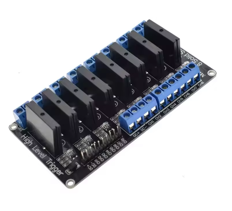
The 8-Channel Solid State Relay Module (AC to DC Control) is a versatile and robust switching solution designed to control high-power AC loads using a wide range of low-voltage DC control signals. Unlike standard SSRs that require a fixed control voltage, this module accepts any DC input from 3V to 24V, making it exceptionally flexible for integration into nearly any system — from 3.3V microcontrollers to 24V industrial PLCs.
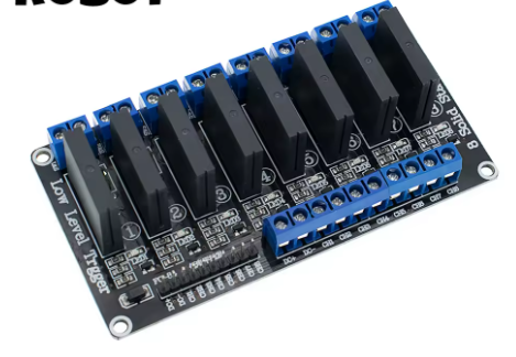
Each channel provides complete optical isolation between the low-voltage control side and the high-voltage AC load side, ensuring safety and noise immunity. The module supports both high-level and low-level trigger modes, allowing you to configure it for active-HIGH or active-LOW logic without additional components. Built-in LED indicators per channel provide clear visual feedback of relay status.
This module is the ideal choice for engineers, integrators, and hobbyists who need a single relay board that works across multiple projects with different control voltages — no need to stock separate 5V, 12V, and 24V versions.
Features
-
Wide DC control voltage range: 3V – 24V (one module works everywhere)
-
Optically isolated control and load sides
-
Selectable high-level or low-level trigger per channel
-
Zero-crossing switching for reduced EMI and longer load life
-
Silent, vibration-resistant, maintenance-free operation
-
LED indicators for each channel
-
Controls AC loads up to 240V / 2A per channel
-
Screw terminals for secure AC wiring
-
Compact 8-channel layout for panel mounting
Technical Parameters
Usage Guide
1. Connecting Control Signals (3V – 24V DC)
The module’s control side accepts any DC voltage between 3V and 24V. Connect as follows:
No jumper or voltage selector is needed — the module automatically works across the full range.
2. Selecting Trigger Mode
Each channel (or the whole bank) can be configured for:
-
High-Level Trigger (HL) : Relay turns ON when control pin is HIGH (≥ 2.5V for 3.3V logic, up to 24V)
-
Low-Level Trigger (LL) : Relay turns ON when control pin is LOW (≤ 1V)
Use the onboard jumper or DIP switches to set the desired mode before operation.
3. AC Load Wiring
Each relay channel has two screw terminals:
Connect the AC neutral wire directly to the load’s neutral terminal.
AC Live ──→ SSR IN ──→ SSR OUT ──→ Load ──→ AC Neutral
⚠️ Always disconnect AC mains before wiring. Use appropriate enclosures.
4. Sample Wiring Scenarios
5. Sample Arduino Code (5V system, High-Level Trigger)
int relayPins[8] = {2,3,4,5,6,7,8,9};
void setup() {
for (int i = 0; i < 8; i++) {
pinMode(relayPins[i], OUTPUT);
digitalWrite(relayPins[i], LOW);
}
}
void loop() {
digitalWrite(relayPins[0], HIGH);
delay(1000);
digitalWrite(relayPins[0], LOW);
delay(1000);
}
6. Important Notes
-
The wide 3V–24V control range applies to both VCC and signal inputs — you can use 3.3V logic with a 5V VCC, or 5V logic with a 12V VCC, etc.
-
Total current draw on VCC depends on how many channels are active. For 8 channels simultaneously, ensure your power supply can deliver ≥100mA.
-
SSRs have a small leakage current (~1-5mA) when OFF — not recommended for extremely sensitive loads like single high-brightness LEDs.
Q: What makes this different from a standard 5V or 12V SSR module?
Standard SSR modules require a fixed control voltage (e.g., 5V only). This wide-voltage module accepts any DC voltage from 3V to 24V on both VCC and control inputs. One module works with 3.3V microcontrollers, 5V Arduinos, 12V PLCs, and 24V industrial systems — no need to buy different versions.
Q: Can I mix different control voltages on different channels?
Yes, but with a shared VCC. All channels share the same VCC voltage. However, signal voltages can vary as long as they are referenced to the same GND. For mixed-voltage systems, use the lowest common VCC or use external level shifters.
Q: Does this module work with 3.3V logic (ESP32, Raspberry Pi)?
Absolutely. Connect VCC to 3.3V (or a separate 5V supply if needed), and the 3.3V logic signals will trigger the relays correctly in High-Level mode. This is a key advantage over standard 5V-only SSR modules.
Q: How do I configure high-level vs low-level trigger?
Use the onboard jumper or DIP switch per channel (or globally, depending on the version). Set to HL for active-HIGH (most microcontrollers), or LL for active-LOW (some PLCs or emergency-stop logic). Check the silkscreen on your specific board version.
Q: Can I control DC loads with this module?
No. This module is designed exclusively for AC loads (50/60Hz). Using it for DC loads will prevent the SSR from turning off. For DC load control, please see our DC-to-DC SSR modules.
Q: What is the maximum current per channel?
The rated maximum is 2A per channel for resistive AC loads (e.g., heaters, incandescent lamps). For inductive loads (motors, transformers, pumps), derate to ≤1A per channel to ensure reliable operation and long life.
Q: Why does my LED lamp glow faintly when the SSR is OFF?
SSRs contain internal snubber circuits that allow a small leakage current (typically 1–5mA). Very sensitive LED bulbs may glow dimly. Solution: Connect a 10kΩ–100kΩ resistor (1/2W or higher) in parallel with the load to absorb the leakage current.
Q: Do I need a heatsink for this module?
For most applications under 1A per channel with intermittent switching, no heatsink is required. For continuous operation at 2A per channel, or when multiple channels are active for extended periods, we recommend adding a fan or mounting the module to a metal plate for heat dissipation.
Q: Can I use this module with a manual switch instead of a microcontroller?
Yes. Connect VCC and GND to a 3V–24V DC power supply. Connect a switch between VCC and INx (for High-Level mode) or between GND and INx (for Low-Level mode). This creates a simple, silent, high-power AC switch.
Q: Is this module suitable for business / industrial applications?
Yes, it is widely used in:
-
Industrial machine retrofits (mixing old 24V PLCs with new AC loads)
-
Building automation (HVAC, lighting, signage)
-
Greenhouse and agricultural controls (pumps, fans, heaters)
-
Commercial kitchen equipment
-
Laboratory and test equipment
The wide voltage range makes it a favorite for integrators who work with multiple control system standards.
Q: What happens if I apply more than 24V to the control side?
Exceeding 24V DC on VCC or any control input will permanently damage the optocoupler and driver circuits. Always stay within the 3V–24V range.
Q: How many switching cycles can this SSR handle?
SSRs typically exceed 100 million switching cycles due to no mechanical wear. This makes them ideal for high-frequency applications such as temperature PID control, flashing signs, or pulse-width modulation (PWM) of AC loads (at low frequencies, e.g., ≤10Hz).