Product Overview
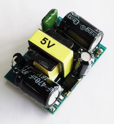
The 5V 700mA AC-DC Buck Converter (Old Version) is an industrial-grade, encapsulated switching power supply module designed to convert high-voltage AC mains (85V–265V) into a regulated 5V DC output. Rated at 3.5 Watts (5V @ 700mA), this compact solution eliminates bulky traditional transformers and provides a safe, efficient, and space-saving way to power microcontrollers, relays, LED indicators, and IoT devices directly from a wall outlet .
Unlike consumer USB chargers, this bare-board module is designed for embedded integration. It features an isolated flyback topology, ensuring complete electrical separation between the hazardous AC side (Live/Neutral) and the low-voltage DC side (5V/GND). This isolation protects your sensitive electronics (Arduino, ESP32) and users from potential shocks .
This”Old Version” refers to the classic open-frame design (approx. 30x20x18mm) that has been a staple in DIY and industrial control for years. It includes comprehensive protection features—overcurrent, short-circuit, and temperature protection—making it a reliable choice for permanent installation in appliances, automation panels, and smart home devices .
Key Features
-
Industrial-Grade Safety Isolation: High voltage isolation between AC input and DC output. Input and output are completely separated, ensuring user safety and protecting downstream low-voltage circuits .
-
Wide Universal Input Range: Accepts 85V to 265V AC (50/60Hz) or DC 100V-370V, making it compatible with global mains standards (110V, 220V, 240V) without any jumper settings .
-
Sufficient 3.5W Power Capacity: Provides a steady 5V output with 700mA of continuous current (800mA peak). Perfect for powering Arduino boards, ESP8266, relays, LED strips, and small sensors .
-
“Old Style” Open-Frame Design: Features a classic non-encapsulated PCB with clear pin headers and mounting holes, allowing for easy soldering or glue fixation directly onto motherboards .
-
Comprehensive Protection Suite: Built-in overcurrent protection (OCP), short-circuit protection (SCP), and over-temperature protection (OTP) prevent damage to the power supply and your devices during faults .
-
Efficient Switching Topology: Achieves up to 85% conversion efficiency with low ripple (≤60mV), utilizing a high-frequency transformer to minimize size and heat compared to linear power supplies .
-
Precision Voltage Regulation: Uses a 431 voltage reference circuit to maintain a stable DC 5V output (±0.2V) even when the input voltage fluctuates .
-
Reliable Performance at Load: Guarantees stable operation across the full 0-700mA output range with an output voltage rise time of less than 100ms .
Technical Specifications (Old Version)
Pinout & Connection Guide
The “Old Version” module typically features 4 pins (2 for AC Input, 2 for DC Output) arranged in a straight line or 2×2 configuration. Always verify the labeling on your specific board as the “Old Version” may have slight variations.
Input Terminals (AC High Voltage Side)
Output Terminals (DC Low Voltage Side)
(Note for the “Old Version”): Some variants may have an additional ground pin or no pin labels. In such cases, trace the circuit: the large electrolytic capacitor on the output side connects to Vout (+) and GND (-). The components on the AC side connect to L and N .
Usage Guide
Step 1: Safety First
⚠️ DANGER: This module deals with high voltage (85-265V AC). Always ensure the device is UNPLUGGED during wiring. Secure all AC wiring with proper insulation (heat shrink or electrical tape) to prevent shorts.
Handling Note for “Old Version”: Do not touch the bottom of the PCB or any conductive components while the module is powered. The underside contains high-voltage traces. Always mount this version on a standoff or use an insulating pad .
Step 2: Wire the AC Input (Mains Side)
-
Use 20-24 AWG wire suitable for mains voltage.
-
Connect the Live wire to the L pin and the Neutral wire to the N pin.
-
Tip: It is recommended to add a fuse (e.g., 1A slow-blow) in series with the Live wire and a switch for safety in permanent installations.
Step 3: Connect the DC Load
Step 4: Power On and Test
-
Double-check all connections for shorts.
-
Plug the module into a standard AC outlet.
-
Do not touch any part of the AC side once powered, especially the exposed leads on the”Old Version” board.
-
The module will instantly provide regulated 5V DC power. Use a multimeter to verify the output voltage before connecting expensive loads.
Application Note: Mounting
Because the “Old Version” is open-frame, avoid mounting it directly on conductive metal surfaces. Use the four corners mounting holes (or glue fixation) to secure it to a plastic enclosure or PCB standoffs to prevent short circuits .
Q: What is the difference between the "Old Version" and the "New Version" of this module?
The specifications (5V 700mA) are generally identical. The difference is primarily physical and component sourcing. The “Old Version” often refers to the open-frame design (no plastic housing) that is slightly larger (30x20x18mm) and may have different pin spacing. The “Old Version” does not have a plastic casing, requiring more care regarding insulation .
Q: Is this module truly isolated?
Yes. It utilizes a high-frequency transformer to provide complete galvanic isolation between the dangerous AC input and the low-voltage DC output. You can touch the 5V output wires without risk (though you should never touch the AC side) .
Q: Can I use this to power an Arduino directly?
Yes. This module is excellent for powering an Arduino, ESP32, or similar board directly from a wall outlet. Connect the 5V output to the Arduino’s 5V pin (not VIN) and the GND to GND .
Q: Why are there 4 pins on the output side?
Typically, there are only 2 output pins (5V and GND). However, some “Old Version” boards may have extra pins for stability or unused NC pins. Use a multimeter to confirm which two pins provide the 5V power .
Q: What are the Black and Red wires included in some "Old Version" kits?
These are pre-crimped output leads (Red=5V+, Black=GND). They are convenient for connecting to your load without soldering, but they are not long enough to reach the AC mains socket .
Q: Can I use this module while it is running at full load (700mA)?
Yes. It is designed for 700mA continuous duty. At close to full load, the module will generate some heat. Ensure adequate airflow and that the ambient temperature stays below 60°C .
Q: Why does the 5V output measure 4.8V when idling?
The specification allows a tolerance of ±0.2V (4.8V – 5.2V). This slight variation is standard for simple switch-mode supplies and is well within the operating limits of all 5V microcontrollers. Under a slight load, it usually settles at 5.0V .
Q: How do I protect this module from short-circuit damage?
The module already includes Short Circuit Protection (SCP) . If the output is shorted, the module will shut down to protect itself. Once the short is removed, the module usually recovers automatically (or may require a brief power cycle depending on the specific component lot) .
Q: Can I glue the "Old Version" module into place?
Yes. The datasheets suggest “glue in fixed” as an installation method. Use non-conductive epoxy or hot glue on the non-conductive areas of the PCB to secure it inside an enclosure .
Q: Is it safe to use this module to power LED strip lights?
Yes, as long as your LED strip consumes less than 3.5 Watts (700mA at 5V). For example, a 5V LED strip with 30 LEDs/m typically draws about 0.5-0.8A per meter; keep the length under 0.5 meters to stay within the 700mA limit .