BESTEP 1-way electromagnetic relay module with dual optocoupler isolation supports high and low trigger 3.3V

SKU: FA2082-0-2
Control Voltage

3.3V – 5V DC

Trigger Mode

High/Low Selectable (Jumper)

Coil Voltage (Relay)

5V DC

Contact Capacity

10A @ 250V AC / 10A @ 30V DC

Contact Type

1 Form C (SPDT)

Isolation

Dual Optocoupler

Operating Temperature

-25°C to +70°C

Dimensions

Approx. 50mm x 26mm x 18mm

Product Overview

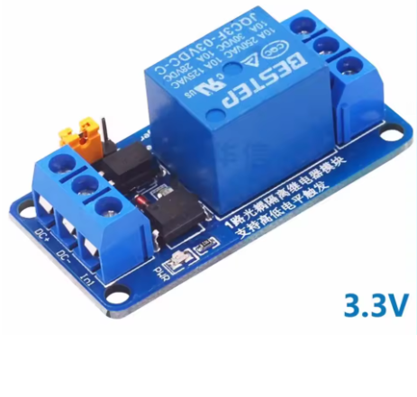
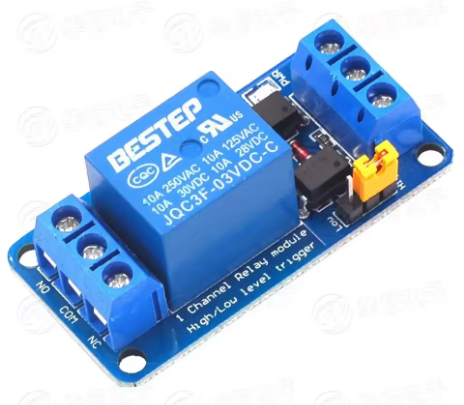
The BESTEP 1-Way Electromagnetic Relay Module is a versatile industrial-grade component designed to interface low-voltage logic circuits with high-power devices. Featuring dual optocoupler isolation, this module provides a robust physical barrier between your sensitive control circuit (such as an Arduino, ESP32, or Raspberry Pi) and the high-voltage load side, effectively eliminating electrical noise and protecting against voltage spikes.

This module supports both High-Level and Low-Level Trigger modes, making it compatible with virtually any microcontroller or digital logic system without the need for external level shifters. Whether you are controlling household appliances with a 5V Arduino or industrial equipment with a 3.3V ESP32, this module offers a safe and reliable switching solution.

Key Features

  • Dual Optocoupler Isolation: Provides two layers of isolation for enhanced noise immunity and safety, preventing interference from inductive loads.

  • Universal Trigger Modes: Supports both High Level (Active HIGH) and Low Level (Active LOW) input, selectable via onboard jumper.

  • Wide Logic Compatibility: Operates reliably with control voltages from 3.3V to 5V, suitable for both 3.3V (ESP32, STM32) and 5V (Arduino) logic systems.

  • High Power Switching: Capable of switching loads up to 10A @ 250V AC or 10A @ 30V DC.

  • SPDT Contact Configuration: Features Common (COM), Normally Open (NO), and Normally Closed (NC) terminals for flexible wiring.

  • Visual Indicators: Onboard LED provides real-time feedback on power status and relay activation.

  • Standard Interface: Equipped with screw terminals for the high-voltage side and pin headers for the control side, facilitating easy integration.

Technical Specifications

Parameter Specification
Control Voltage 3.3V – 5V DC
Trigger Mode High/Low Selectable (Jumper)
Coil Voltage (Relay) 5V DC
Contact Capacity 10A @ 250V AC / 10A @ 30V DC
Contact Type 1 Form C (SPDT)
Isolation Dual Optocoupler
Operating Temperature -25°C to +70°C
Dimensions Approx. 50mm x 26mm x 18mm

Pinout & Interface Guide

  • Control Side (Low Voltage):

    • VCC: Connect to 3.3V or 5V (depending on your microcontroller).

    • GND: Connect to ground.

    • IN: Control signal input.

  • Load Side (High Voltage):

    • COM: Common terminal.

    • NO: Normally Open (connects to COM when relay is activated).

    • NC: Normally Closed (connects to COM when relay is off).

  • Jumper: Selects the trigger mode (High Level or Low Level).

Usage Guide

Wiring Instructions

  1. Connect Power: Connect the VCC and GND pins to your microcontroller’s power and ground.

  2. Set Trigger Mode: Place the jumper on the “High” or “Low” position according to your control logic.

  3. Connect Load: For safe testing, connect a low-voltage LED circuit to the COM and NO terminals. For high-voltage wiring (e.g., 220V), ensure the power source is disconnected before wiring.

  4. Control: Send a HIGH or LOW signal from your microcontroller to the IN pin.

Example Code (Arduino)

cpp
// Define the control pin
int relayPin = 7;

void setup() {
  pinMode(relayPin, OUTPUT);
  // If set to "Low Level Trigger", the relay activates when the pin is LOW.
  // If set to "High Level Trigger", the relay activates when the pin is HIGH.
  digitalWrite(relayPin, HIGH); // Start with relay off (for High Trigger)
}

void loop() {
  digitalWrite(relayPin, LOW);  // Activate Relay (depends on jumper setting)
  delay(5000);
  digitalWrite(relayPin, HIGH); // Deactivate Relay
  delay(5000);
}

Q: What is the difference between High-Level and Low-Level trigger?

High-Level trigger activates the relay when the control pin receives a positive voltage (e.g., 3.3V or 5V). Low-Level trigger activates the relay when the control pin is connected to Ground (0V). The onboard jumper lets you select which mode fits your system best.

Q: Can I power this module directly from a 3.3V ESP32?

Yes. The module is designed to accept 3.3V logic, making it a perfect companion for modern 3.3V microcontrollers like the ESP32, ESP8266, or Raspberry Pi Pico.

Q: Why are there two optocouplers?

Dual optocouplers provide enhanced isolation. One optocoupler typically handles the input signal, while the other ensures the relay coil drive circuit is fully isolated. This offers superior protection against electrical noise and spikes generated by motors or solenoids.

Q: What happens if I set the jumper incorrectly?

If the jumper is set to High Trigger but your code sends a LOW signal, the relay will not activate (and vice versa). Simply adjust the jumper position to match your code or hardware logic.

Q: Do I need a flyback diode for inductive loads?

The module already includes built-in flyback protection on the relay coil, protecting the low-voltage circuit. However, if you are switching a large motor or solenoid, adding an external flyback diode across the load terminals is still recommended to extend the relay’s contact life.

Q: Can I use this to control 220V AC appliances?

Yes, the relay contacts are rated for 250V AC at 10A. It is suitable for controlling lights, fans, and other household appliances. Always ensure proper electrical safety precautions are taken when working with high voltage.

Q: The LED is on but the relay isn't clicking.

If the status LED is illuminated but you do not hear a click, check if the VCC voltage is stable (5V if using the relay’s coil). If the voltage is too low (e.g., attempting to run the 5V relay coil on 3.3V), the relay may not engage.