


DESCRIPTION
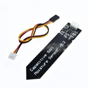
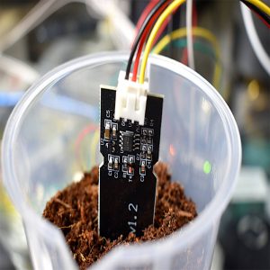
The Capacitive Soil Moisture Sensor Module determines the amount of soil moisture by measuring changes in capacitance to determine the water content of soil. This can be used in an automatic plant watering system or to signal an alert of some type when a plant needs watering.
PACKAGE INCLUDES:
- Capacitive Soil Moisture Sensor Module
- 3-wire interface cable, 8″ long
KEY FEATURES OF CAPACITIVE SOIL MOISTURE SENSOR MODULE:
- Analog output of moisture content
- More corrosion resistant than resistive type of sensor
- 3.3 or 5V operation. Low power so may be driven from digital pin on MCU
This soil moisture sensor module uses capacitance rather than resistance to determine the water content of soil. The main down-side to the common fork type resistance sensor is that the probes inserted into the soil must be conductive bare metal and the small electrical current that flows between them results in corrosion of the probes through electrolysis over time.
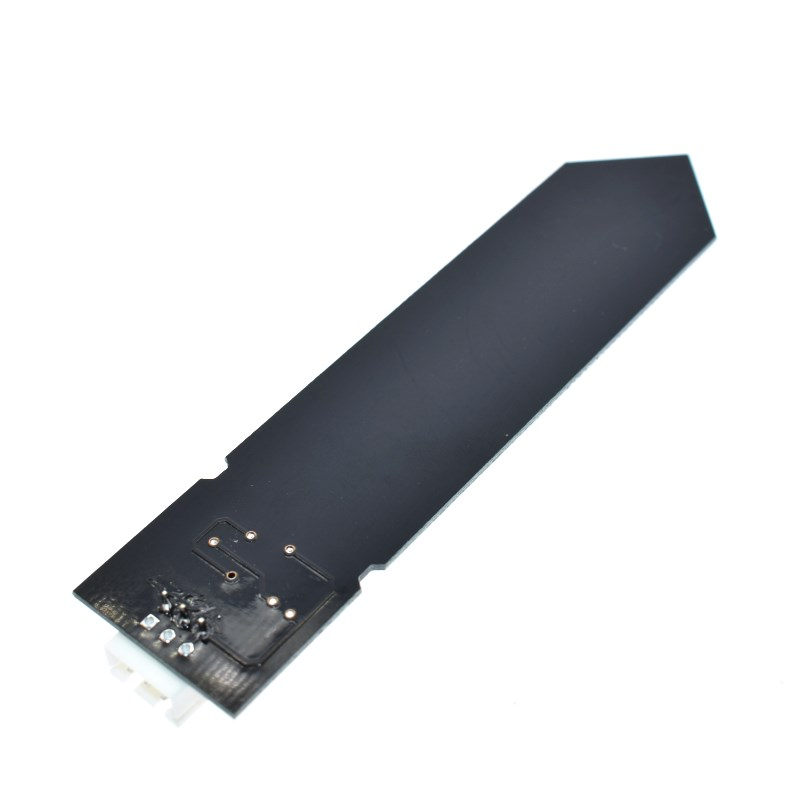
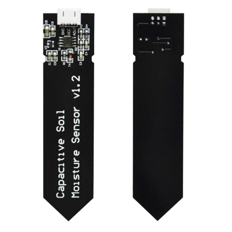
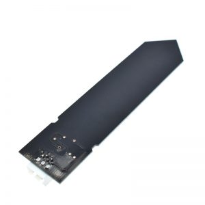
The capacitive probe improves that situation because the sensor metal inserted into the soil can be covered in solder resist to minimize corrosion and electrical current is not flowing through the soil to induce electrolysis. The main weakness in the lifespan of the probe is the uncoated cut sides of the PCB which can absorb moisture over time as well as the exposed electronics at the top of the probe if they get splashed by water. The customer can add further protective coating such as clear fingernail polish or similar coating if desired without seriously affecting the performance of the probe.
Theory of Operation
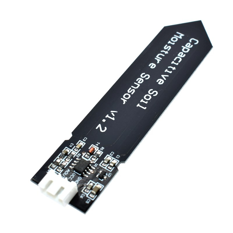
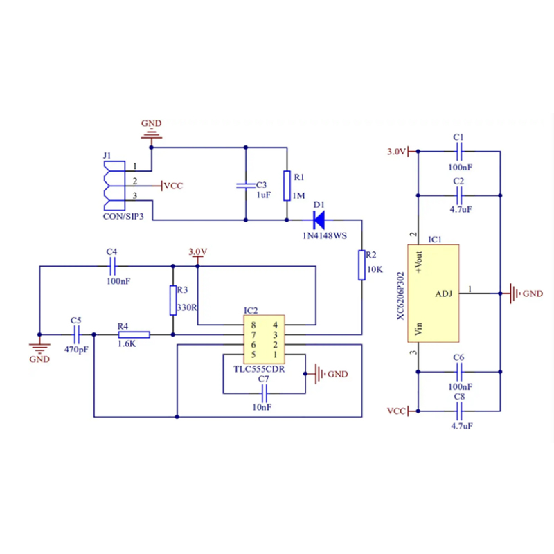
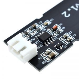
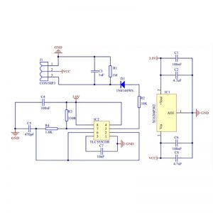
The module uses a TL555I CMOS timer to create a 1.5MHz clock. The TL555I is similar to the ubiquitous NE555 but is newer CMOS technology with a higher frequency capability and other improvements.
A peak voltage detector converts the waveform from the TL555I into a DC voltage that can be read by the ADC input of a microcontroller.
When the probe is exposed to moisture, it affects the capacitance of the circuit which in turn affects the peak amplitude of the signal and therefore the DC voltage output that is being monitored by the MCU. Higher moisture = lower DC voltage output.
If you want to do a deep dive into the theory of how this thing works including schematics, there is an interesting though somewhat technical read where researchers reverse engineered how modules of this type work. Characterization of Low-Cost Capacitive Soil Moisture Sensors for IoT Networks
Basic Usage
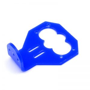
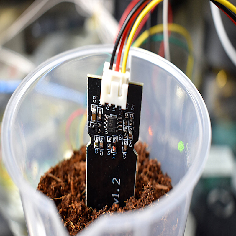
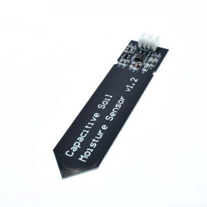
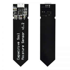
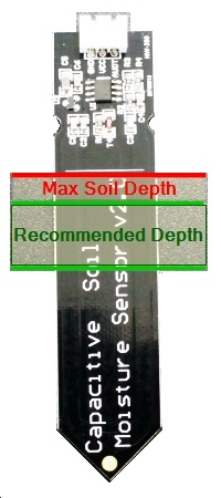 The probe is inserted into the soil to be monitored. The horizontal line shows the maximum depth that the probe should be inserted. The green area shown to the right is the recommended depth to place the probe. It is important that the electronics at the top of the probe are not subject to water or water splashing to avoid damage.
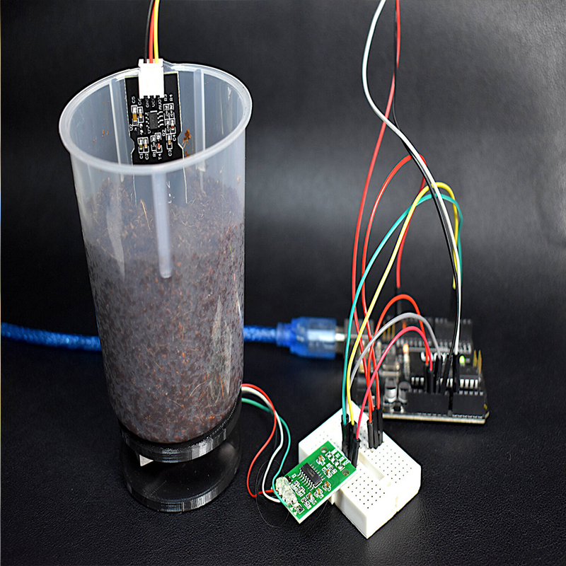
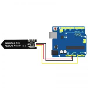
The analog output of the probe is monitored by the analog input on an MCU like an Arduino.
The measurement range between wet soil and dry soil is determined experimentally by measuring the soil under different conditions and the software configured to detect when the soil is too dry, too wet or just right.
More complete details below under Our Evaluation Results.
Module Connections
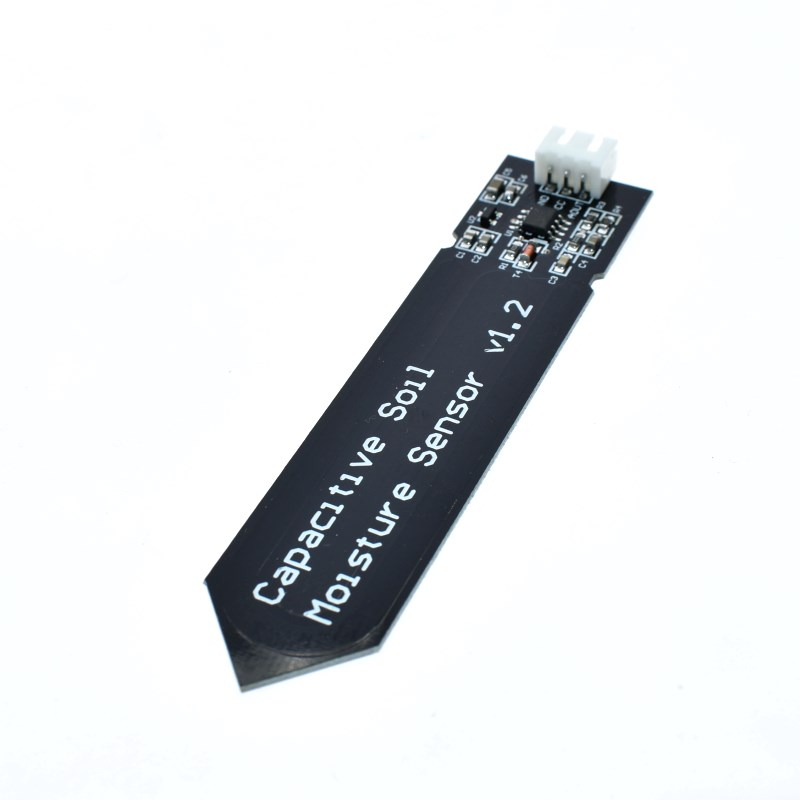
There is a 3-pin JST PH2.0 type connector on the probe. One end of the supplied cable plugs into the connector and the other end is a standard Dupont style 3-pin female connector. The cable is color coded with black for ground, red for VCC and yellow for AOUT
1×3 Connector
- GND = Ground, must be common with the MCU
- VCC = 3.3V – 5.5VDC. May be powered from a digital output pin on a MCU
- AOUT = Analog output usually connected to an analog input on a MCU
OUR EVALUATION RESULTS:
It is not possible to directly define an actual percentage of moisture in the soil from the measurements taken, but it is fairly straightforward to define basic ranges for what would be considered ‘too dry’, ‘too wet’ and ‘just right’.
This simple program can be used to monitor the output of the probe under different conditions to calibrate the settings. Just hook the sensor output to A0 and apply power and ground. male/male jumper wires can be used to connect the sensor connector to the MCU if needed. Once downloaded, open the Serial Monitor window to view the output of the sensor.
void setup() {
  Serial.begin(9600); // open serial port, set the baud rate as 9600 bps
}
void loop() {
  int val;
  val = analogRead(0); //connect sensor to Analog 0
  Serial.println(val); //print the value to serial port
  delay(5000);
}
To determine the possible measurement extremes, the probe output can be measured with the probe in the open air and then when submerged up to the Max line in a glass of water. That will determine the approximate maximum boundaries for the expected measurements. On the wet end of the scale, the cup of water may not read quite as wet as very wet soil due to factors other than just the amount of moisture present.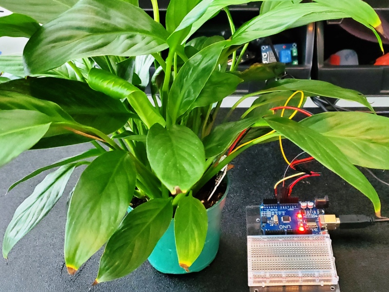
Using a potted plant, measure the soil under 3 basic conditions:
- When dry enough so that the plant should be watered
- When watered so it has the desired amount of moisture that would be considered ideal for the plant
- When just watered heavily so the soil is on the too wet side and not ideal for the plant.
From those 5 measurements, ranges for each of the 3 conditions can be initially determined and then honed in on once the setup goes into operation. It also depends a bit on how overall dry or wet a particular species of plant likes to be.
On most MCUs like Arduino, the ADC is 10-bit, so the measurement has a range of 0-1023. In our test setup we got the following readings:
- Dry in open air = 590-600
- Dry soil needing water > 380
- Ideal soil moisture = 277 – 380
- Just watered soil = 273
- In cup of water = 277
Based on that data, the program below defines the following ranges:
- < 275 is too wet
- = 275 – 380 is the target range
- > 380 is dry enough that we should water the poor thing.
The program reports the status but doesn’t do anything with it. The trip point could be used to light an LED if the soil gets too dry or turn on power to a small water pump to automatically water the plant. I found it convenient to wire a red and green LED on the MCU I was experimenting with. Green meant everything was fine and Red indicated the plant was either too wet or too dry and needed attention without being connected to a computer to see the output.
Power is supplied from a digital output pin so it can be turned on/off under MCU control since the sensor may only need to be read every few hours. When power is first applied, the circuit takes a while to stabilize on the reading, so in the example the software waits 10 seconds after applying power before a reading is taken.
The program is using pin A0 for the analog reading but this can be any analog pin. Similarly pin 9 is being used to power the module, but these can be changed to any digital pin as needed.